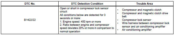
Toyota RAV4 (XA40) 2013-2018 Service Manual: Compressor lock sensor circuit
![]()
Description
This sensor sends 1 pulse per engine revolution to the air conditioning amplifier. If the ratio of the compressor speed divided by the engine speed is smaller than a predetermined value, the air conditioning amplifier turns the compressor off, and the indicator blinks at approximately 1 second intervals.
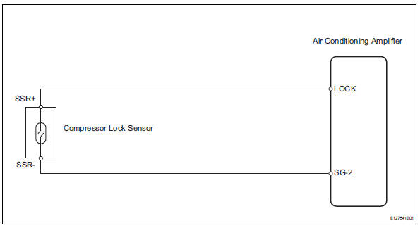
Wiring diagram
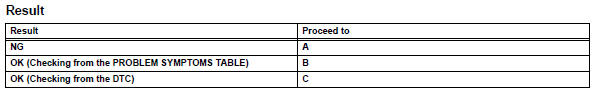
Inspection procedure
- Check air conditioning amplifier (lock signal)
- Remove the air conditioning amplifier with its connectors still connected.
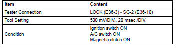
- Check the waveform of the amplifier connector.
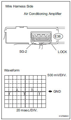
Ok:
waveform is as shown in the illustration.

- Inspect compressor lock sensor
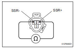
- Disconnect the b47 compressor lock sensor connector.
- Measure the resistance of the sensor.
Standard resistance 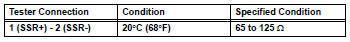

- Check wire harness (compressor lock sensor - air conditioning amplifier)
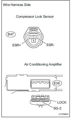
- Disconnect the b47 compressor lock sensor connector.
- Disconnect the e36 amplifier connector.
- Measure the resistance of the wire harness side connectors.
Standard resistance 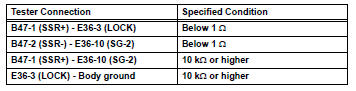

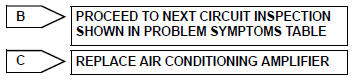
Replace air conditioning amplifier
 Evaporator temperature sensor circuit
Description
The no. 1 Cooler thermistor (evaporator temperature sensor) is installed on
the evaporator in the air
conditioning unit to detect the temperature of the cooled air that has passed ...
 Pressure sensor circuit
Description
This dtc is output when the refrigerant pressure is either extremely low
(0.19 Mpa [2.0 Kgf/cm2, 28 psi]
or less) or extremely high (3.14 Mpa [32.0 Kgf/cm2, 455 psi] or more). The ...
Other materials:
Removal (2005/11-2006/01)
Disconnect cable from negative battery
terminal
Caution:
Wait at least 90 seconds after disconnecting the
cable from the negative (-) battery terminal to
prevent airbag and seat belt pretensioner activation.
Remove front door scuff plate lh
Using a screwdriver, detach the 10 cla ...
Seat heater switch
Components
Removal
Disconnect cable from negative battery
terminal
Caution:
Wait at least 90 seconds after disconnecting the
cable from the negative (-) battery terminal to
prevent airbag and seat belt pretensioner activation.
Remove switch base (see page ip-18)
Remove seat he ...
Instrument panel
Engine switch
Starting the engine/changing the modes
Emergency stop of the engine
When the engine will not start
Warning messages*1
Shift lever
Changing the shift position
Precautions against towing
When the shift lever does not move
Meters
Reading the meters/adjusting the instrument pa ...
