Toyota RAV4 (XA40) 2013-2018 Service Manual: Pressure sensor circuit
![]()
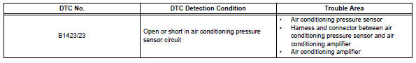
Description
This dtc is output when the refrigerant pressure is either extremely low (0.19 Mpa [2.0 Kgf/cm2, 28 psi] or less) or extremely high (3.14 Mpa [32.0 Kgf/cm2, 455 psi] or more). The air conditioning pressure sensor, which is installed on the pipe of the high pressure side, detects the refrigerant pressure and sends refrigerant pressure signals to the air conditioning amplifier. The air conditioning amplifier determines the pressure from the signals in accordance with the sensor characteristics, and controls the compressor accordingly.
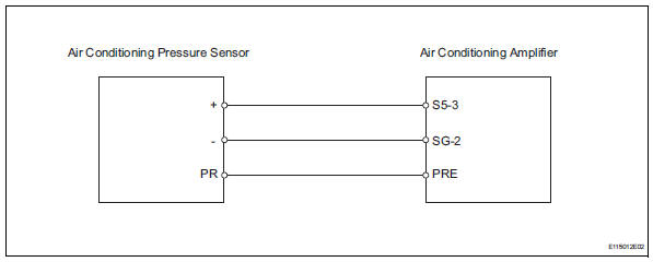
Wiring diagram
Inspection procedure
- Check refrigerant
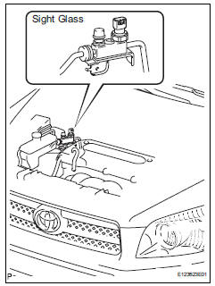
- Check the sight glass of the cooler unit refrigerant liquid pipe.
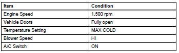
- Prepare the vehicle in accordance with the chart
below.
- Compare the sight glass to the following chart.
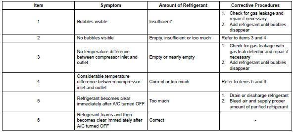
Hint:
*: If the ambient temperature is higher than usual but cooling is sufficient, bubbles in the sight glass are permissible.


- Read value of intelligent tester (reg press sens)
- Connect the intelligent tester (with can vim) to the dlc3.
- Turn the ignition switch on and turn the intelligent tester main switch on.
- Select the item below in the data list, and read the value displayed on the intelligent tester.
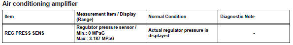
Ok: the display is as specified in the normal condition column.

- Check wire harness (pressure sensor - air conditioning amplifier)
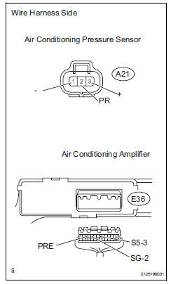
- Disconnect the a21 pressure sensor connector.
- Disconnect the e36 amplifier connector.
- measure the resistance of the wire harness side connectors.
Standard resistance 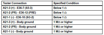

- Check air conditioning amplifier
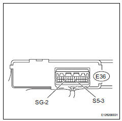
- Remove the air conditioning amplifier with its connectors still connected.
- Measure the resistance of the wire harness side connector
Standard resistance 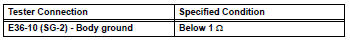
- Turn the ignition switch on.
- Measure the voltage of the wire harness side connector.
Standard voltage 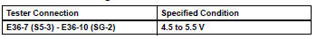


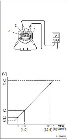
- Inspect air conditioning pressure sensor
- Turn the a/c switch on.
- Disconnect the a21 sensor connector.
- Connect the three 1.5 V dry cell batteries' positive (+)
lead to terminal 3 and the negative (-) lead to terminal 1.
Then connect the voltmeter's positive (+) lead to terminal 2 and the negative (-) lead to terminal 1. Measure the voltage.
Ok: the voltage changes in accordance with the refrigerant pressure as shown in the graph.

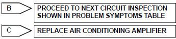
Replace air conditioning amplifier
 Compressor lock sensor circuit
Description
This sensor sends 1 pulse per engine revolution to the air conditioning
amplifier. If the ratio of the
compressor speed divided by the engine speed is smaller than a predetermined ...
 Compressor solenoid circuit (2005/11-2006/01)
Description
In this circuit, the compressor receives a refrigerant compression demand
signal from the air conditioning
amplifier. Based on this signal, the compressor changes the degree of
r ...
Other materials:
Different diameter tire malfunction
Description
The skid control ecu measures the speed of each wheel by receiving signals
from the speed sensor.
These signals are used for recognizing that all 4 wheels are operating properly.
Therefore, all wheel
signals must be equal.
Inspection procedure
Check tire size
...
Cd player operation
Insert disc or select “cd” on the audio source selection screen
with a disc inserted to begin listening to a cd.
Audio control screen
Pressing the “audio” button displays the audio control screen from
any screens of the selected source.
Audio source selection screen
appears
Displ ...
Diagnostic trouble code chart
If a dtc is displayed during the dtc check, check the circuit
listed in the table below and proceed to the page given.
Hint:
*1: "Comes on" means the malfunction indicator lamp
(mil) illuminates.
*2: "Dtc stored" means the ecm memorizes the
malfunction code if the ecm ...
