Toyota RAV4 (XA40) 2013-2018 Service Manual: Front airbag sensor lh circuit malfunction
Description
The front airbag sensor lh consists of the diagnostic circuit, the frontal deceleration sensor, etc.
If the center airbag sensor receives signals from the frontal deceleration sensor, it determines whether or not the srs should be activated.
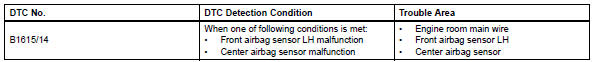
Dtc b1615/14 is recorded when a malfunction is detected in the front airbag sensor lh circuit.
Wiring diagram
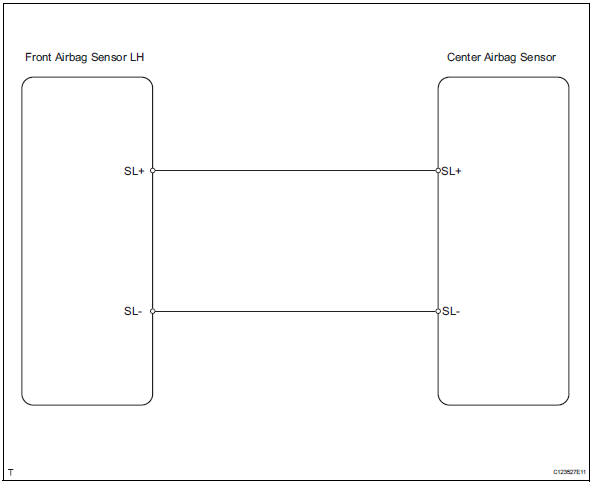
Inspection procedure
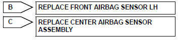
- Check front airbag sensor lh
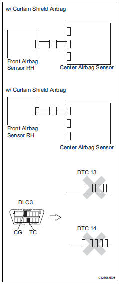
- Turn the ignition switch off.
- Disconnect the cable from the negative (-) battery terminal, and wait for at least 90 seconds.
- Interchange the front airbag sensor rh and lh, and connect the connectors to them.
- Connect the cable to the negative (-) battery terminal, and wait for at least 2 seconds.
- Turn the ignition switch on, and wait for at least 60 seconds.
- Clear the dtcs (see page rs-49).
- Turn the ignition switch off
- Turn the ignition switch on, and wait for at least 60 seconds.
- Check the dtcs (see page rs-49).
Result 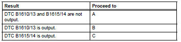
Hint:
Dtcs other than dtc b1610/13 and b1615/14 may be output at this time, but they are not related to this check.

Use simulation method to check
 Front airbag sensor rh circuit malfunction
Description
The front airbag sensor rh consists of the diagnostic circuit, the frontal
deceleration sensor, etc.
If the center airbag sensor assembly receives signals from the frontal
dece ...
 Driver side - side airbag sensor circuit malfunction
Description
The side airbag sensor lh consists of part including the diagnostic circuit
and the lateral deceleration
sensor.
When the center airbag sensor receives signals from the lateral ...
Other materials:
Location of the interior lights
Rear interior light
Front interior lights/personal lights
Open tray lights (if equipped)*
Footwell lights (if equipped)*
Front cup holder lights (if equipped)*
*: These lights turn on when a door is unlocked.
When the shift lever is in a position other than P, the brightness of these
ligh ...
Glossary of sae and toyota terms
This glossary lists all sae-j1930 terms and abbreviations
used in this manual in compliance with sae
recommendations, as well as their toyota equivalents.
...
Differential case
Components
Disassembly
Remove front differential ring gear
Place the matchmarks on the ring gear and
differential case.
Remove the 14 bolts.
Using a plastic-faced hammer, tap on the ring gear
to remove it from the case.
Remove front differential case ...
