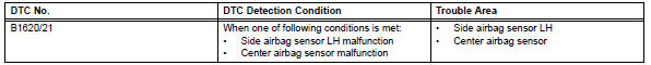
Toyota RAV4 (XA40) 2013-2018 Service Manual: Driver side - side airbag sensor circuit malfunction

Description
The side airbag sensor lh consists of part including the diagnostic circuit and the lateral deceleration sensor.
When the center airbag sensor receives signals from the lateral deceleration sensor, it determines whether or not the srs should be activated.
Dtc b1620/21 is set when a malfunction is detected in the side airbag sensor lh circuit.
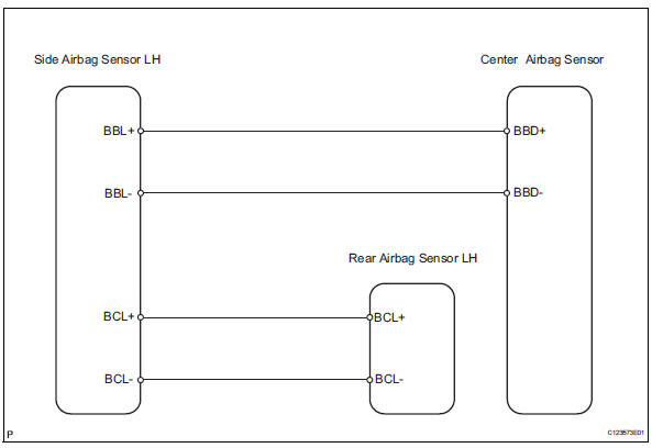
Wiring diagram
Inspection procedure
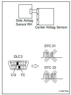
- Check side airbag sensor lh
- Turn the ignition switch off.
- Disconnect the cable from the negative (-) battery terminal, and wait for at least 90 seconds.
- Interchange the side airbag sensor rh and the side airbag sensor lh, and connect the connectors to them.
- Connect the cable to the negative (-) battery terminal, and wait for at least 2 seconds.
- Turn the ignition switch on, and wait for at least 60 seconds.
- Clear the dtcs (see page rs-49).
- Turn the ignition switch off.
- Turn the ignition switch on, and wait for at least 60 seconds.
- Check the dtcs (see page rs-49).
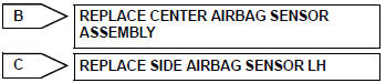
Result 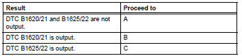
Dtcs other than dtc b1620/21 and b1625/22 may be output at this time, but they are not related to this check.

Use simulation method to check
 Front airbag sensor lh circuit malfunction
Description
The front airbag sensor lh consists of the diagnostic circuit, the frontal
deceleration sensor, etc.
If the center airbag sensor receives signals from the frontal deceleration
sens ...
 Lost communication with driver side - side airbag sensor assembly
Description
The side airbag sensor lh consists of part including the diagnostic circuit
and the lateral deceleration
sensor.
When the center airbag sensor receives signals from the lateral ...
Other materials:
System description
Driver seat belt warning light
When the driver seat belt is not fastened with the
ignition switch on, the driver seat belt warning light
on the combination meter comes on to inform the
driver. The center airbag sensor detects the driver
seat belt status and sends signals to the
co ...
Dtc check / clear
Check dtc
Connect the intelligent tester (with can vim) to the
dlc3.
Turn the ignition switch on and turn the intelligent
tester on.
Read the dtc by following the prompts on the
tester screen.
Hint:
Refer to the intelligent tester operator's manual for
further details.
...
Checking the coolant
The coolant level is satisfactory
if it is between the "FULL" and
"LOW" lines on the reservoir
when the engine is cold.
Reservoir cap
"FULL" line
"LOW" line
If the level is on or below the "LOW" line, add coolant up to the "FULL"
line.
â– Coolant selection
Only use "Toyota Super Long Life
Cool ...
