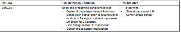
Toyota RAV4 (XA40) 2013-2018 Service Manual: Lost communication with driver side - side airbag sensor assembly

Description
The side airbag sensor lh consists of part including the diagnostic circuit and the lateral deceleration sensor.
When the center airbag sensor receives signals from the lateral deceleration sensor, it determines whether or not the srs should be activated.
Dtc b1622/81 is set when a malfunction is detected in the side airbag sensor lh circuit.
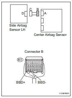
Wiring diagram
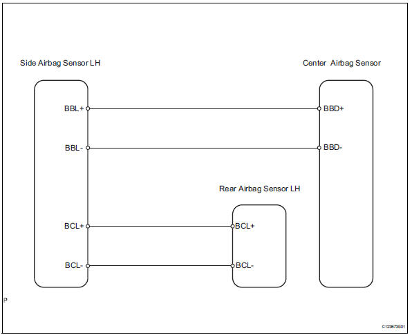
Inspection procedure
- Check connection of connector
- Turn the ignition switch off.
- Disconnect the cable from the negative (-) battery terminal, and wait for at least 90 seconds.
- Check that the connectors are properly connected to the center airbag sensor, rear airbag sensor lh and the side airbag sensor lh.
Ok: the connectors are properly connected.

- Check floor wire (open)
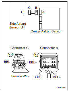
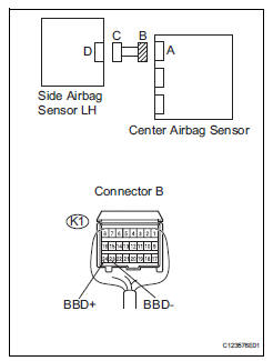
- Disconnect the connectors from the center airbag sensor and the side airbag sensor lh.
- Using a service wire, connect k8-4 (bbl+) and k8-3 (bbl-) of connector c.
Notice:
Do not forcibly insert the service wire into the terminals of the connector when connecting.
- Measure the resistance of the wire harness side connector.
Standard resistance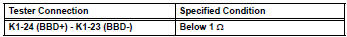

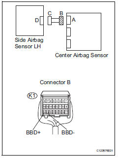
- Check floor wire (short)
- Disconnect the service wire from connector c.
- Measure the resistance of the wire harness side connector
Standard resistance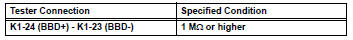

- Check floor wire (to b+)
- Connect the cable to the negative (-) battery terminal, and wait for at least 2 seconds.
- Turn the ignition switch on.
- Measure the voltage of the wire harness side connector.
standard voltage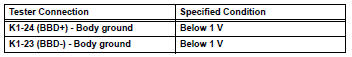

- Check floor wire (to ground)
- Turn the ignition switch off.
- Disconnect the cable from the negative (-) battery terminal, and wait for at least 90 seconds.
- Measure the resistance of the wire harness side connector.
Standard resistance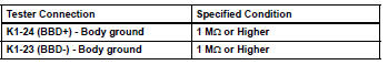


- Check side airbag sensor lh
- Connect the connectors to the center airbag sensor.
- Interchange the side airbag sensor rh with the side airbag sensor lh and connect the connectors to them.
- Connect the cable to the negative (-) battery terminal, and wait for at least 2 seconds.
- Turn the ignition switch on, and wait for at least 60 seconds.
- Clear the dtcs (see page rs-49).
- Turn the ignition switch off.
- Turn the ignition switch on, and wait for at least 60 seconds.
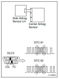
- Check for dtcs (see page rs-49).
Result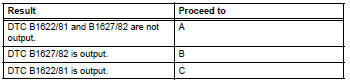


Hint:
Dtcs other than dtc b1622/81 and b1627/82 may be output at this time, but they are not related to this check.
Use simulation method to check
 Driver side - side airbag sensor circuit malfunction
Description
The side airbag sensor lh consists of part including the diagnostic circuit
and the lateral deceleration
sensor.
When the center airbag sensor receives signals from the lateral ...
 Driver side - side airbag sensor assembly initialization incomplete
Description
The side airbag sensor lh consists of part including the diagnostic circuit
and the lateral deceleration
sensor.
When the center airbag sensor receives signals from the lateral ...
Other materials:
Precaution
Handling precautions for srs airbag
system
Handling precautions for srs airbag system (see
page rs-1).
Handling precautions for steering
column
When handling the steering column assembly.
Avoid any impact to the steering column
assembly, especially to the motor or ...
Insufficient coolant temperature for closed loop fuel control
Description
Refer to dtc p0115 (see page es-105).
Monitor description
The resistance of the ect sensor varies in proportion to the actual ect. The
ect supplies a constant
voltage to the sensor and monitors the signal output voltage of the sensor. The
signal voltage output
varies acc ...
Reporting safety defects
for u.S. Owners
If you believe that your vehicle has a defect which could cause a
crash or could cause injury or death, you should immediately
inform the national highway traffic safety administration
(nhtsa) in addition to notifying toyota motor sales, u.S.A., Inc.
(Toll-free: 1-800-331-4331).
If nhtsa re ...
