Toyota RAV4 (XA40) 2013-2018 Service Manual: Headlight dimmer switch
Precaution
- Precaution for vehicle with srs
- Some procedures in this section may affect the supplemental restraint system (srs). Prior to performing the procedures, read the srs section's "precaution" (see page rs-1).
Components
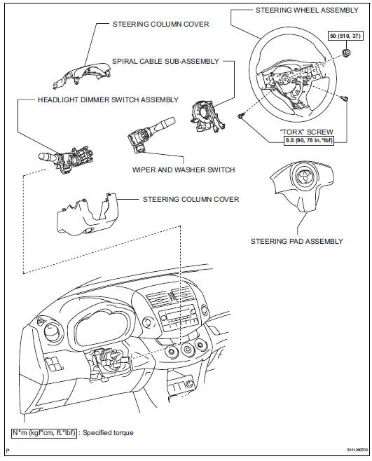
Removal
- Disconnect cable from negative battery terminal
Caution:
Wait at least 90 seconds after disconnecting the cable from the negative (-) battery terminal to prevent airbag and seat belt pretensioner activation.
- Place front wheels facing straight ahead
- Remove steering pad assembly (see page rs- 336)
- Remove steering wheel assembly (see page sr-12)
- Remove steering column cover (see page sr-12)
- Remove spiral cable sub-assembly (see page rs-346)
- Remove wiper and washer switch (see page ww-27)
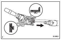
- Remove headlight dimmer switch assembly
- Disconnect the connector.
- Using needle-nose pliers, remove the band clamp as shown in the illustration.
- Using a screwdriver, detach the claws and remove the switch.
Hint:
Tape the screwdriver tip before use.
Inspection
- Inspect headlight dimmer switch assembly
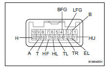
- Measure the resistance of the switch.
Standard resistance:
Light control switch 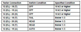
Headlight dimmer switch 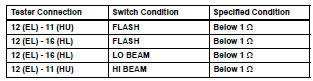
Turn signal switch 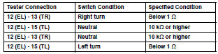
Fog light switch 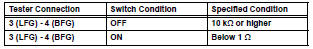
If the result is not as specified, replace the dimmer switch assembly.
Installation
- Install headlight dimmer switch assembly
- Attach the claw to install the headlight dimmer switch with the claw as shown in the illustration.
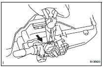
- Install the headlight dimmer switch with the clamp.
- Connect the connector.
- Install wiper and washer switch assembly (see page ww-29)
- Install spiral cable sub-assembly (see page rs-347)
- Install steering column cover (see page sr- 20)
- Install steering wheel assembly (see page sr-21)
- Place front wheels facing straight ahead
- Inspect steering wheel center point
- Install steering pad assembly (see page rs- 336)
- Connect cable to negative battery terminal
- Inspect steering pad assembly (see page rs- 337)
- Check srs warning light
- Check the srs warning light (see page rs-337).
 Footwell light
On-vehicle inspection
Inspect footwell light
Connect the battery's positive (+) lead to terminal 2
and the negative (-) lead to terminal 1, then check
that the light comes on.
Ok: ...
 Hazard warning switch
Components
Removal
Disconnect cable from negative battery
terminal
Caution:
Wait at least 90 seconds after disconnecting the
cable from the negative (-) battery terminal to
prevent ai ...
Other materials:
Problem symptoms table
Hint:
Use the table below to help determine the cause of the
problem symptom. The potential causes of the symptoms
are listed in order of probability in the "suspected area"
column of the table. Check each symptom by checking the
suspected areas in the order they are listed. Re ...
Luggage cover (if
equipped)
â– Installing the luggage cover
1. Compress the both ends of
the luggage cover and insert
into the recess to install.
2. Pull out the luggage cover
and hook it onto the anchors.
â– Removing the luggage
cover
1. Release the cover from the
left and right anchors and
allow it to retract.
2. Compre ...
Adjusting the settings
To adjust the fan speed, turn the fan speed control dial clockwise
(increase) or counterclockwise (decrease).
Turning the dial to “0” turns off the fan.
To adjust the temperature setting, turn the temperature control dial
clockwise (warm) or counterclockwise (cool).
If is ...
