Toyota RAV4 (XA40) 2013-2018 Service Manual: Hazard warning switch
Components
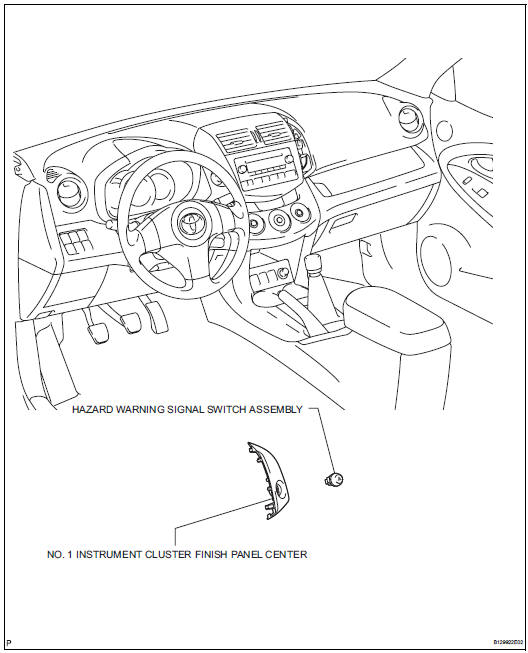
Removal
- Disconnect cable from negative battery terminal
Caution:
Wait at least 90 seconds after disconnecting the cable from the negative (-) battery terminal to prevent airbag and seat belt pretensioner activation.
- Remove no. 1 Instrument cluster finish panel center (see page ip-5)
- Remove hazard warning signal switch assembly
- Detach the 2 claws and remove the switch.
Inspection
- Inspect hazard warning signal switch assembly
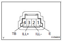
- Measure the resistance of the switch.
Standard resistance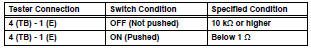
If the result is not as specified, replace the switch assembly.
- Inspect the switch illumination.
- Connect the battery positive (+) lead to terminal 3 (ill+) and the negative (-) lead to terminal 2 (ill-), then check that the light comes on.
Ok: led comes on.
If the result is not as specified, replace the light.
Installation
- Install hazard warning signal switch assembly
- Attach the 2 claws to install the switch.
- Install no. 1 Instrument cluster finish panel center (see page ip-10)
- Connect cable to negative battery terminal
 Headlight dimmer switch
Precaution
Precaution for vehicle with srs
Some procedures in this section may affect the
supplemental restraint system (srs). Prior to
performing the procedures, read the srs section's
...
 Front door courtesy switch
Components
Removal
Hint:
Use the same procedures for the rh and lh sides.
The procedures listed below are for the lh side.
Disconnect cable from negative battery
terminal
Cautio ...
Other materials:
Monitor drive pattern
Test monitor drive pattern for ect
Caution:
Perform this drive pattern on a level surface and
strictly observe the posted speed limits and traffic
laws while driving.
Hint:
Performing this drive pattern is one method to simulate
the ect's malfunction detection conditions.
The dtcs may ...
Intake air temperature circuit malfunction
Description
The intake air temperature (iat) sensor, mounted on the mass air flow (maf)
meter, monitors the iat.
The iat sensor has a built-in thermistor with a resistance that varies according
to the temperature of the
intake air. When the iat is low, the resistance of the thermist ...
Maintenance requirements
To ensure safe and economical
driving, day-to-day care
and regular maintenance
are essential. It is the
owner's responsibility to
perform regular checks.
Toyota recommends the following
maintenance:
â– Repair and replacement
It is recommended that genuine
Toyota parts be used for repairs to
ensure ...
