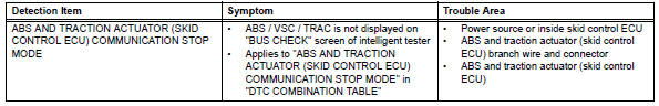
Toyota RAV4 (XA40) 2013-2018 Service Manual: Abs and traction actuator (skid control ecu) communication stop mode
Description
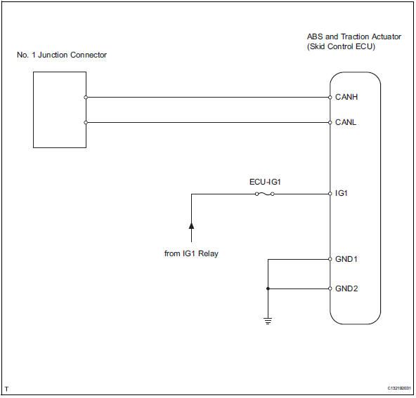
Wiring diagram
Inspection procedure
Notice:
- Turn the ignition switch off before measuring the resistances of the main wire and the branch wire.
- After the ignition switch is turned off, check that the key reminder warning system and light reminder warning system are not in operation.
- Before measuring the resistance, leave the vehicle for at least 1 minute and do not operate the ignition switch, any switches or doors. If doors need to be opened in order to check connectors, open the doors and leave them open.
Hint:
Operating the ignition switch, any switches or any doors triggers related ecu and sensor communication with the can, which causes resistance variation.
- Check can bus line disconnection (abs and traction actuator branch wire)
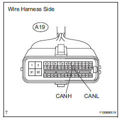
- Disconnect the a19 abs and traction actuator (skid control ecu) connector.
- Measure the resistance of the wire harness side connector.
Standard resistance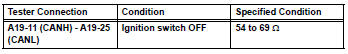

- Check wire harness (abs and traction actuator - battery and body ground)
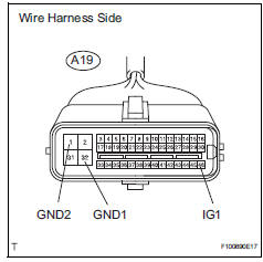
- Disconnect the a19 abs and traction actuator (skid control ecu) connector.
- Measure the resistance of the wire harness side connector.
Standard resistance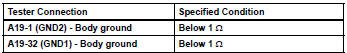
- Measure the voltage of the wire harness side connector.
Standard voltage 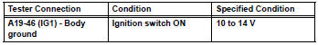

Replace abs and traction actuator (skid control ecu)
 Fail-safe chart
Fail-safe function
When communication fails in any of the main wires
(communication lines) due to a short circuit or other
causes, the fail-safe function, which is specified for
each sy ...
 Air conditioning amplifier communication stop mode
Description
Wiring diagram
Inspection procedure
Notice:
Turn the ignition switch off before measuring the resistances
of the main wire and the branch
wire.
After the ignition ...
Other materials:
Installation
Install accelerator pedal rod
Install the accelerator pedal rod with the 2 bolts.
Torque: 5.4 N*m (55 kgf*cm, 48 in.*Lbf)
Connect the accelerator pedal position sensor
connector.
Connect cable to negative battery terminal
...
Installation
Install ecm
Install the 2 brackets to the ecm with the 4 screws.
Torque: 3.0 N*m (30 kgf*cm, 27 in.*Lbf)
Connect the 2 ecm connectors.
Notice:
When connecting the connector, make sure that
dirt, water and other foreign matter does not
become stuck between the connector and ...
Programming HomeLink
â– Before programming
HomeLink
During programming, it is possible
that garage doors,
gates, or other devices may
operate. For this reason,
make sure that people and
objects are clear of the
garage door or other devices
to prevent injury or other
potential harm.
It is recommended that a n ...
