Toyota RAV4 (XA40) 2013-2018 Service Manual: Air conditioning amplifier communication stop mode
Description
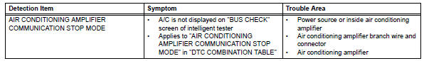
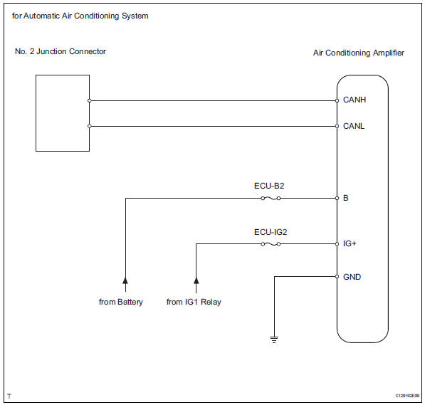
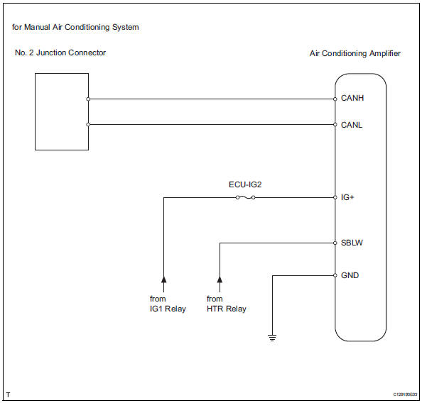
Wiring diagram
Inspection procedure
Notice:
- Turn the ignition switch off before measuring the resistances of the main wire and the branch wire.
- After the ignition switch is turned off, check that the key reminder warning system and light reminder warning system are not in operation.
- Before measuring the resistance, leave the vehicle for at least 1 minute and do not operate the ignition switch, any switches or doors. If doors need to be opened in order to check connectors, open the doors and leave them open.
Hint:
Operating the ignition switch, any switches or any doors triggers related ecu and sensor communication with the can, which causes resistance variation.
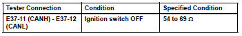
- Check can bus line for disconnection (air conditioning amplifier branch wire)
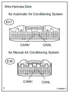
- Disconnect the e37*1 or e36*2 air conditioning amplifier connector.
Hint:
- *1: For automatic air conditioning system.
- *2: For manual air conditioning system.
- Measure the resistance of the wire harness side connector.
Standard resistance:
for automatic air conditioning system
For manual air conditioning system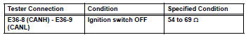

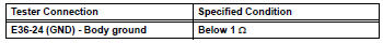
- Check wire harness (air conditioning amplifier - battery and body ground)
- Disconnect the e37*1 or e36*2 air conditioning amplifier connector.
Hint:
- *1: For automatic air conditioning system.
- *2: For manual air conditioning system.
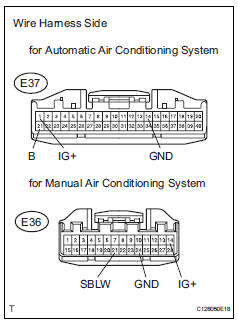
- Measure the resistance of the wire harness side connectors.
Standard resistance:
for automatic air conditioning system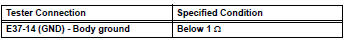
For manual air conditioning system
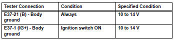
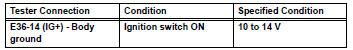
- Measure the voltage of the wire harness side connector.
Standard voltage:
for automatic air conditioning system
For manual air conditioning system

Replace air conditioning amplifier
 Abs and traction actuator (skid control ecu) communication stop mode
Description
Wiring diagram
Inspection procedure
Notice:
Turn the ignition switch off before measuring the resistances
of the main wire and the branch
wire.
After the ignition swi ...
 Power steering ecu communication stop mode
Description
Wiring diagram
Inspection procedure
Notice:
Turn the ignition switch off before measuring the resistances of the
main wire and the branch
wire.
After the ignition swi ...
Other materials:
For vehicles with supplemental restraint system
The rav4 is equipped with a supplemental restraint
system (srs). The srs of this vehicle consists of the
following:
Steering pad
Front passenger airbag assembly
Front seat side airbag assembly
Front seat outer belt assembly with pretensioner
Curtain shield
Center airbag sensor
Fron ...
Opening and closing procedures
The power windows can be opened and closed using the switches.
Operating the switch moves the windows as follows:
Closing
One-touch closing (driver’s window
only) (if equipped)*
Opening
One-touch opening (driver’s
window only)*
*: To stop the window partway, operate
the ...
System description
Brief description
The can (controller area network) is a serial data
communication system for real time application. It is
a vehicle multiplex communication system which
has a high communication speed (500 kbps) and
the ability to detect malfunctions.
By pairing the canh and canl ...
