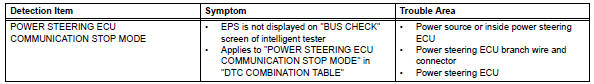
Toyota RAV4 (XA40) 2013-2018 Service Manual: Power steering ecu communication stop mode
Description
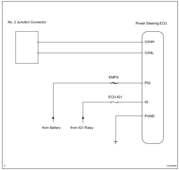
Wiring diagram
Inspection procedure
Notice:
- Turn the ignition switch off before measuring the resistances of the main wire and the branch wire.
- After the ignition switch is turned off, check that the key reminder warning system and light reminder warning system are not in operation.
- Before measuring the resistance, leave the vehicle for at least 1 minute and do not operate the ignition switch, any switches or doors. If doors need to be opened in order to check connectors, open the doors and leave them open.
Hint:
Operating the ignition switch, any switches or any doors triggers related ecu and sensor communication with the can, which causes resistance variation.
- Check can bus line for disconnection (power steering ecu main wire)
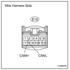
- Disconnect the e18 power steering ecu connector.
- Measure the resistance of the wire harness side connector.
Standard resistance 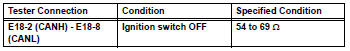

- Check wire harness (power steering ecu - battery and body ground)
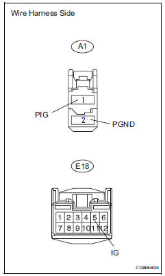
- Disconnect the a1 and e18 power steering ecu connectors.
- Measure the resistance of the wire harness side connector.
Standard resistance 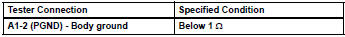
- Measure the voltage of the wire harness side connectors.
Standard voltage 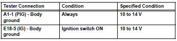

Replace power steering ecu
 Air conditioning amplifier communication stop mode
Description
Wiring diagram
Inspection procedure
Notice:
Turn the ignition switch off before measuring the resistances
of the main wire and the branch
wire.
After the ignition ...
 Steering angle sensor communication stop mode
Description
Wiring diagram
Inspection procedure
Notice:
Turn the ignition switch off before measuring the resistances of the
main wire and the branch
wire.
After the ignition swi ...
Other materials:
Removal
Hint:
Use the same procedures for the rh side and lh side.
The procedures listed below are for the rh side.
Remove front seat headrest assembly
Remove front seat assembly
Operate the power seat switch knob and move the
seat to the foremost position.
Using a screwdriver, d ...
Ig power source circuit
Description
This is the main power source supplied to the air conditioning amplifier when
the ignition switch is on
(ig). This power source is used for operating components, such as the air
conditioning amplifier and
servo motors.
Wiring diagram
Inspection procedure
Inspect fuse (ec ...
AHB (Automatic High
Beam)
The Automatic High Beam
uses an in-vehicle front
camera to assess the brightness
of streetlights, the
lights of vehicles ahead etc.,
and automatically turns the
high beams on or off as necessary.
WARNING
â– Limitations of the Automatic
High Beam
Do not overly rely on the Automatic
High Beam. Always ...
