Toyota RAV4 (XA40) 2013-2018 Service Manual: Front wiper motor and link
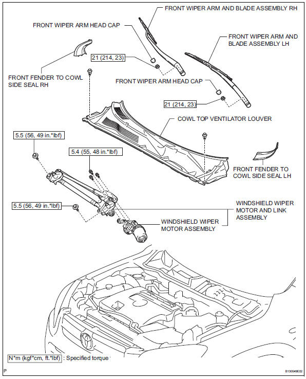
Components
Removal
- Disconnect cable from negative battery terminal
Caution:
Wait at least 90 seconds after disconnecting the cable from the negative (-) battery terminal to prevent airbag and seat belt pretensioner activation.
- Remove front wiper arm head cap
- Remove the 2 caps.
- Remove front wiper arm and blade assembly lh
- Remove the nut and arm and blade.
- Remove front wiper arm and blade assembly rh
- Remove the nut and arm and blade.
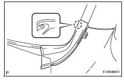
- Remove front fender to cowl side seal lh
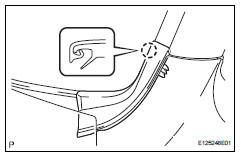
- Detach the claw and remove the front fender to cowl side seal.
- Remove front fender to cowl side seal rh
- Detach the claw and remove the front fender to cowl side seal.
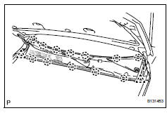
- Remove cowl top ventilator louver

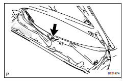
- Remove the 2 clips.
- Detach the 12 claws and remove the louver.
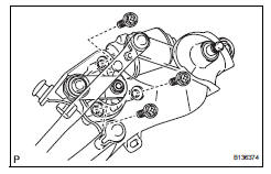
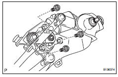
- Remove windshield wiper motor and link assembly
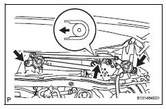
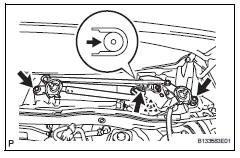
- Remove the 2 bolts.
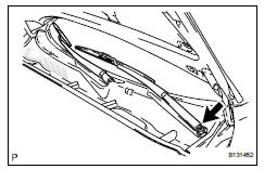
- Move the wiper cushion in the direction shown by the arrow in the illustration to detach the wiper cushion from the body, and remove the wiper motor and link.
- Disconnect the connector and detach the clamp.
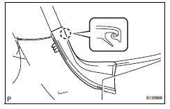
- Remove windshield wiper motor assembly
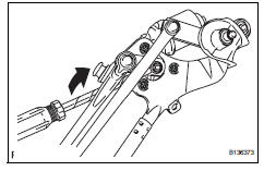
- Using a screwdriver, disconnect the rod of the wiper link from the wiper motor as shown in the illustration.
Hint:
Tape the screwdriver tip before use.
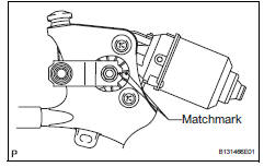
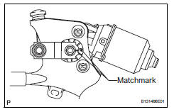
- Put matchmarks on the crank arm and motor, as shown in the illustration.
- Remove the 3 bolts and wiper motor.
Inspection
- Inspect windshield wiper motor assembly
- Check the lo operation.
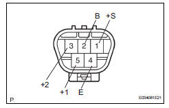
- Connect the battery's positive (+) lead to terminal 5 (+1) and the negative (-) lead to terminal 4 (e), and check that the motor operates at low speed (lo).
Ok: motor operates at low speed (lo).
- Check the hi operation.
- Connect the battery's positive (+) lead to terminal 3 (+2) and the negative (-) lead to terminal 4 (e), and check that the motor operates at high speed (hi).
Ok: motor operates at high speed (hi).
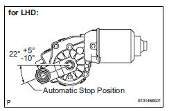
- Check the automatic stop operation.
- Connect the battery's positive (+) lead to terminal 5 (+1) and the negative (-) lead to terminal 4 (e). With the motor rotating at low speed (lo), disconnect terminal 5 (+1) to stop the wiper motor operation at any position other than the automatic stop position.
- Using sst, connect terminals 1 (+s) and 5
(+1). Then connect the battery's positive (+)
lead to terminal 2 (b) and the negative (-) lead
to terminal 4 (e) to restart the motor operation
at low speed (lo).
Sst 09843-18040
- Check that the motor stops automatically at the automatic stop position.
Ok: refer to illustration.
If the result is not as specified, replace the motor assembly.
Installation
- Install windshield wiper motor assembly
- Install the wiper motor with the 3 bolts.
Torque: 5.4 N*m (55 kgf*cm, 48 in.*Lbf)
- Align the matchmarks on the crank arm and motor.
- Apply mp grease to the sliding parts of the wiper motor and the rod of the wiper link.
- Connect the rod of the wiper link to the wiper motor.
- Install windshield wiper motor and link assembly
- Move the wiper motor and link in the direction shown by the arrow in the illustration to attach the wiper cushion to the body, and install the wiper motor and link.
- Install the 2 bolts.
Torque: 5.5 N*m (56 kgf*cm, 49 in.*Lbf)
- Connect the connector.
- Install cowl top ventilator louver
- Attach the 12 claws to install the louver.
- Install the 2 clips.
- Install front fender to cowl side seal lh
- Attach the claw to install the front fender to cowl side seal.
- Install front fender to cowl side seal rh
- Attach the claw to install the front fender to cowl side seal.
- Install front wiper arm and blade assembly rh
- Stop the wiper motor at the automatic stop position.
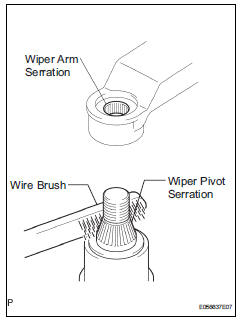
- Clean the wiper arm serration with a round file or equivalent.
- Clean the wiper pivot serration with a wire brush.
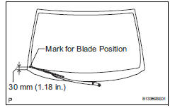
- Install the arm and blade with the nut. Make sure that the arm and blade comes to the position shown in the illustration.
Torque: 21 n*m (214 kgf*cm, 23 ft.*Lbf)
Hint:
Hold down the arm hinge with your hand while tightening the nut.
- Install front wiper arm and blade assembly lh
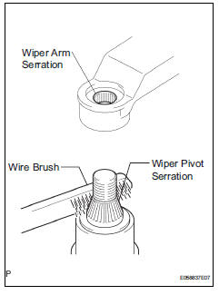
- Clean the wiper arm serration with a round file or equivalent.
- Clean the wiper pivot serration with a wire brush.
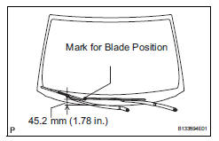
- install the arm and blade with the nut. make sure
that the arm and blade comes to the position shown
in the illustration.
torque: 21 n*m (214 kgf*cm, 23 ft.*lbf)
Hint:
Hold down the arm hinge with your hand while tightening the nut.
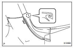
- Operate the front wipers while spraying water or washer fluid on the windshield. Ensure that there is no interference between the blades and pillar.
- Install front wiper arm head cap
- Install the 2 caps.
- Connect cable to negative battery terminal
 Front wiper motor
Inspection
Inspect front wiper motor
Check the lo operation.
Connect the battery's positive (+) lead to
terminal 5 (+1) and the negative (-) lead to
terminal 4 (e), and check t ...
 Front wiper rubber
Components
Removal
Remove front wiper blade
Detach the claw as shown in the illustration.
Remove the wiper blade as shown in the illustration.
Notice:
Do not fold ...
Other materials:
Outside vehicle
General maintenance
Performing the following maintenance checks on the vehicle
is the owner's responsibility. The owner may perform the
maintenance or take the vehicle to a service center. Check
the parts of the vehicle described below on a daily basis. In
most cases, special tools are not requ ...
Bluetooth® phone
settings
You can adjust the hands-free system to your desired settings.
“Phone/message settings” screen
To display the screen shown below, press the “setup” button, and
select “phone” on the “setup” screen.
Set the phone connection
Setting the sound
Contact/call history settings
...
Disposal
Hint:
When scrapping a vehicle equipped with srs or disposing of
the front seat side airbag, be sure to deploy the airbag first in
accordance with the procedure described below. If any
abnormality occurs with the airbag deployment, contact the
service dept. Of toyota motor sales, u.S.A., Inc.
...
