Toyota RAV4 (XA40) 2013-2018 Service Manual: Steering angle sensor communication stop mode
Description
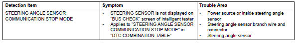
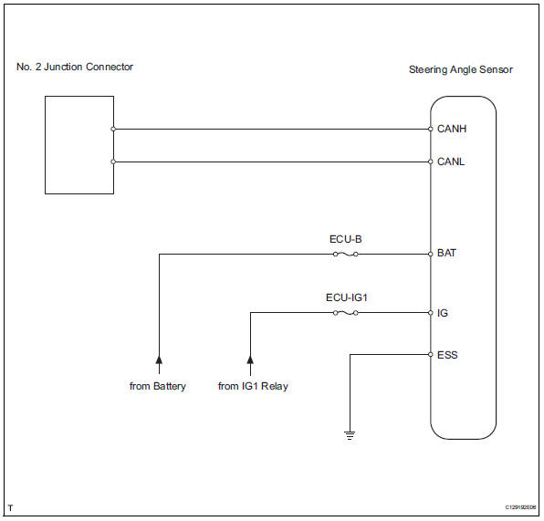
Wiring diagram
Inspection procedure
Notice:
- Turn the ignition switch off before measuring the resistances of the main wire and the branch wire.
- After the ignition switch is turned off, check that the key reminder warning system and light reminder warning system are not in operation.
- Before measuring the resistance, leave the vehicle for at least 1 minute and do not operate the ignition switch, any switches or doors. If doors need to be opened in order to check connectors, open the doors and leave them open.
Hint:
Operating the ignition switch, any switches or any doors triggers related ecu and sensor communication with the can, which causes resistance variation.
- Check can bus line for disconnection (steering angle sensor branch wire)
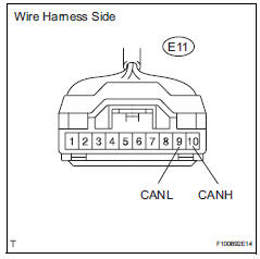
- Disconnect the e11 steering angle sensor connector.
- Measure the resistance of the wire harness side connector.
Standard resistance 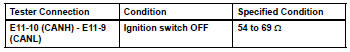

- Check wire harness (steering angle sensor - battery and body ground)
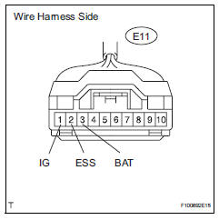
- Disconnect the e11 steering angle sensor connector.
- Measure the resistance of the wire harness side connector.
Standard resistance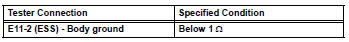
- Measure the voltage of the wire harness side connector.
Standard voltage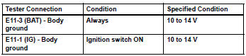

Replace steering angle sensor
 Power steering ecu communication stop mode
Description
Wiring diagram
Inspection procedure
Notice:
Turn the ignition switch off before measuring the resistances of the
main wire and the branch
wire.
After the ignition swi ...
 Yaw rate sensor communication stop mode
Description
Wiring diagram
Inspection procedure
Notice:
Turn the ignition switch off before measuring the resistances of the
main wire and the branch
wire.
After the ignition swi ...
Other materials:
Using the cd player
Power
Volume
Cd eject
Selecting a track or displaying
track list
Searching playback
Random play or back button
Repeat play
Fast-forwarding or rewinding
Changing the audio source/
playback
Playback/pause
Selecting a track
Displaying text message
Loading cds
Insert ...
Wireless remote control
The keys are equipped with the
following wireless remote control:
Vehicles without smart key
system
Locks all the doors
Sounds the alarm
Unlocks all the doors
Opens the side windows*
*: This setting must be customized
at your Toyota dealer.
Vehicles with smart key system
Locks all the do ...
Installation
Install tire pressure warning antenna and receiver
Install the receiver with the bolt.
Torque: 7.5 N*m (76 kgf*cm, 66 in.*Lbf)
Connect the connector.
Install inner roof side garnish assembly
rh (see page ir-52)
Install deck trim side panel assembly rh
(w/o rear no. 2 S ...
