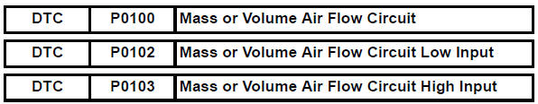
Toyota RAV4 (XA40) 2013-2018 Service Manual: Mass or volume air flow circuit
Description
The mass air flow (maf) meter is a sensor that measures the amount of air flowing through the throttle valve.
The ecm uses this information to determine the fuel injection time and to provide the appropriate air-fuel ratio.
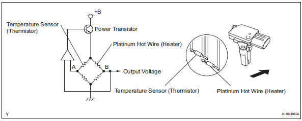
Inside the maf meter, there is a heated platinum wire which is exposed to the flow of intake air.
By applying a specific electrical current to the wire, the ecm heats it to a given temperature. The flow of incoming air cools both the wire and an internal thermistor, affecting their resistance. To maintain a constant current value, the ecm varies the voltage applied to these components in the maf meter. The voltage level is proportional to the airflow through the sensor, and the ecm uses it to calculate the intake air volume.
The circuit is constructed so that the platinum hot wire and the temperature sensor create a bridge circuit, and the power transistor is controlled so that the potentials of a and b remain equal to maintain the predetermined temperature.
Hint:
When any of these dtcs are set, the ecm enters fail-safe mode. During fail-safe mode, the ignition timing is calculated by the ecm, according to the engine rpm and throttle valve position. Fail-safe mode continues until a pass condition is detected.
Hint:
When any of these dtcs are set, check the air-flow rate by selecting the following menu items on the intelligent tester: diagnosis / enhanced obd ii/ data list / primary / maf.
Monitor description
If there is a defect in the maf meter or an open or short circuit, the voltage level deviates from the normal operating range. The ecm interprets this deviation as a malfunction in the maf meter and sets a dtc.
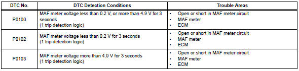
Example: when the sensor output voltage remains less than 0.2 V, or more than 4.9 V, for more than 3 seconds, the ecm sets a dtc.
If the malfunction is not repaired successfully, a dtc is set 3 seconds after the engine is next started.
Monitor strategy
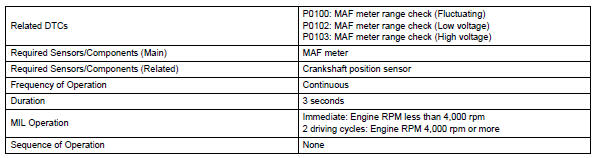
Typical enabling conditions
![]()
Typical malfunction thresholds
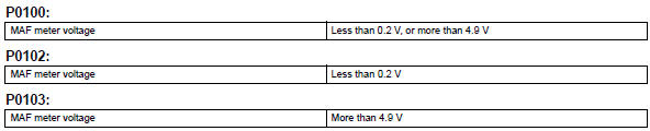
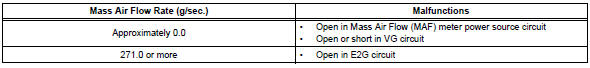
Component operating range
![]()
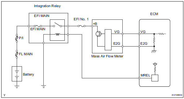
Wiring diagram
Inspection procedure
Hint:
Read freeze frame data using the intelligent tester. Freeze frame data records the engine condition when malfunctions are detected. When troubleshooting, freeze frame data can help determine if the vehicle was moving or stationary, if the engine was warmed up or not, if the air-fuel ratio was lean or rich, and other data from the time the malfunction occurred.
- Read value using intelligent tester (mass air flow rate)
- Connect the intelligent tester to the dlc3.
- Start the engine.
- Turn the tester on.
- Select the following menu items: diagnosis / enhanced obd ii / data list / primary / maf.
- Read the values displayed on the tester.
Result
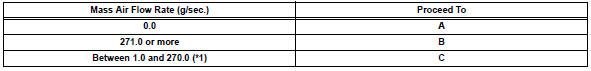
Hint:
*1: The value must change when the throttle valve is
open or closed with the engine running.

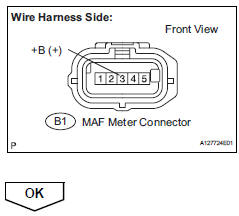
- Inspect mass air flow meter (power source voltage)
- Disconnect the b1 mass air flow (maf) meter connector.
- Turn the ignition switch on.
- Measure the voltage between the terminal of the wire harness side connector and body ground.
Standard voltage 
- Reconnect the maf meter connector.
- Inspect mass air flow meter (vg voltage)
- Output voltage inspection.
- Apply battery voltage across terminals +b and e2g.
- Connect the positive (+) tester probe to terminal vg, and negative (-) tester probe to terminal e2g.
- Measure the voltage.
Standard voltage 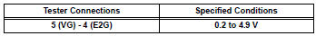
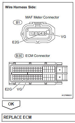
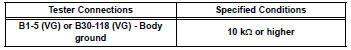
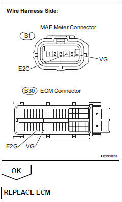
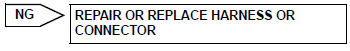
- Check harness and connector (mass air flow meter - ecm)
- Disconnect the b1 maf meter connector.
- Disconnect the b30 ecm connector.
- Measure the resistance.
Standard resistance (check for open)
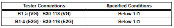
Standard resistance (check for short)
- Reconnect the maf meter connector.
- Reconnect the ecm connector.
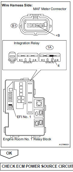
Check harness and connector (mass air flow meter - integration relay)
- Check the efi no. 1 Fuse.
- Disconnect the b1 maf meter connector.
- Remove the integration relay from the engine room no. 1 Relay block.
- Check the resistance.
Standard resistance (check for open)
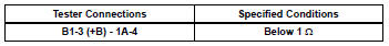
Standard resistance (check for short)
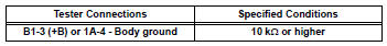
- Reconnect the maf meter connector.
- Reinstall the integration relay.
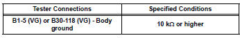
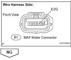
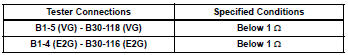
- Check harness and connector (sensor ground)
- Disconnect the b1 maf meter connector.
- Measure the resistance.

- Check harness and connector (mass air flow meter - ecm)
- Disconnect the b1 maf meter connector.
- Disconnect the b30 ecm connector.
- Measure the resistance.
Standard resistance (check for open)
Standard resistance (check for short)
- Reconnect the maf meter connector.
- Reconnect the ecm connector.
 Oxygen (a/f) sensor heater control circuit
Hint:
Although the dtc titles say oxygen sensor, these dtcs relate to the
air-fuel ratio (a/f) sensor.
Sensor 1 refers to the sensor mounted in front of the three-way
catalytic convert ...
 Mass air flow circuit range / performance problem
Description
Refer to dtc p0100 (see page es-86).
Monitor description
The maf meter is a sensor that measures the amount of air flowing through the
throttle valve. The ecm
uses this infor ...
Other materials:
Towing related terms
â– GCWR (Gross Combination
Weight Rating)
The maximum allowable gross
combination weight. The gross combination weight is the sum
of the total vehicle weight
(including the occupants, cargo
and any optional equipment
installed on the vehicle) and the
weight of the trailer being towed
(including the ...
Fog light switch
The fog lights secure excellent visibility in difficult driving
conditions,
such as in rain and fog.
(U.S.A.) Or (canada)
turns the fog lights off
Turns the fog lights on
Fog lights can be used when
The headlights are on in low beam. ...
Shift position purpose
*1: Shifting the shift lever to d allows the system to select a gear suitable
for
the driving conditions.
Setting the shift lever to d is recommended for normal driving.
*2: Selecting shift ranges using s mode restricts the upper limit of the
possible
gear ranges, controls engine bra ...
