Toyota RAV4 (XA40) 2013-2018 Service Manual: Oxygen (a/f) sensor heater control circuit
Hint:
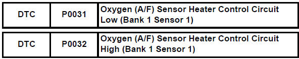
- Although the dtc titles say oxygen sensor, these dtcs relate to the air-fuel ratio (a/f) sensor.
- Sensor 1 refers to the sensor mounted in front of the three-way catalytic converter (twc) and located near the engine assembly.
Description
Refer to dtc p2195 (see page es-292).
Hint:
- When either of these dtcs is set, the ecm enters fail-safe mode. The ecm turns off the a/f sensor heater in fail-safe mode. Fail-safe mode continues until the ignition switch is turned off.
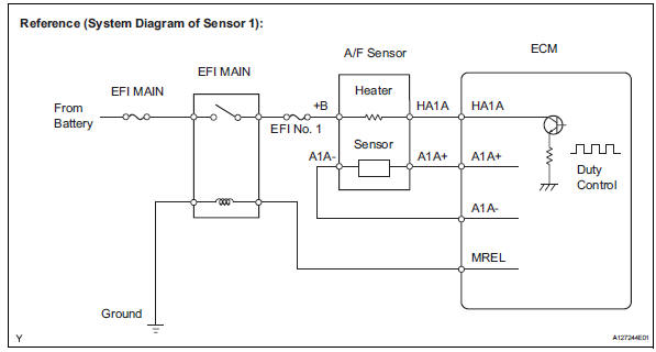
- The ecm provides a pulse width modulated control circuit to adjust the current through the heater. The a/f sensor heater circuit uses a relay on the b+ side of the circuit.
Monitor description
The ecm uses information from the air-fuel ratio (a/f) sensor to regulate the air-fuel ratio and keep it close to the stoichiometric level. This maximizes the ability of the three-way catalytic converter (twc) to purify the exhaust gases.
The a/f sensor detects oxygen levels in the exhaust gas and transmits the information to the ecm. The inner surface of the sensor element is exposed to the outside air. The outer surface of the sensor element is exposed to the exhaust gas. The sensor element is made of platinum coated zirconia and includes an integrated heating element.
The zirconia element generates a small voltage when there is a large difference in the oxygen concentrations between the exhaust gas and outside air. The platinum coating amplifies this voltage generation.
The a/f sensor is more efficient when heated. When the exhaust gas temperature is low, the sensor cannot generate useful voltage signals without supplementary heating. The ecm regulates the supplementary heating using a duty-cycle approach to adjust the average current in the sensor heater element. If the heater current is outside the normal range, the signal transmitted by the a/f sensor becomes inaccurate, as a result, the ecm is unable to regulate air-fuel ratio properly.
When the current in the a/f sensor heater is outside the normal operating range, the ecm interprets this as a malfunction in the sensor heater and sets a dtc.
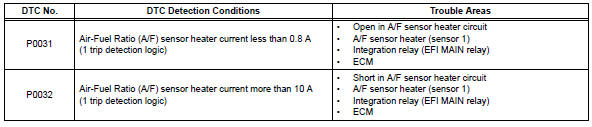
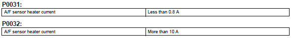
Example: the ecm sets dtc p0032 when the current in the a/f sensor heater is more than 10 a. Conversely, when the heater current is less than 0.8 A, dtc p0031 is set.
Monitor strategy
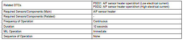
Typical enabling conditions
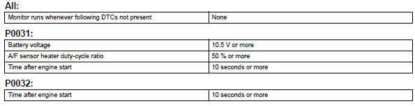
Typical malfunction thresholds
Component operating range
![]()
Wiring diagram
Refer to dtc p2195 (see page es-296).
Inspection procedure
Hint:
Read freeze frame data using the intelligent tester. Freeze frame data records the engine condition when malfunctions are detected. When troubleshooting, freeze frame data can help determine if the vehicle was moving or stationary, if the engine was warmed up or not, if the air-fuel ratio was lean or rich, and other data from the time the malfunction occurred.
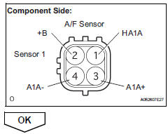
- Inspect air-fuel ratio sensor (heater resistance)
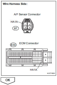
- Disconnect the b7 a/f sensor connector.
- Measure the resistance of the a/f sensor connector.
Standard resistance 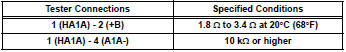
- Reconnect the a/f sensor connector.
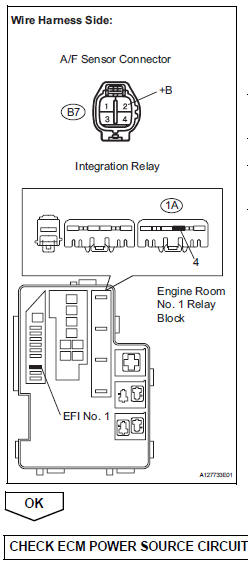
- Check terminal voltage (+b of a/f sensor)
- Disconnect the b7 a/f sensor connector.
- Turn the ignition switch on.
- Measure the voltage between the terminals of the b7 a/f sensor connector and body ground.
Standard voltage 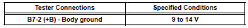
- Reconnect the a/f sensor connector.

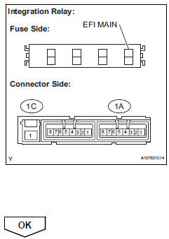
- Inspect integration relay (efi main relay)
- Remove the integration relay from the engine room no. 1 Relay block.
- Inspect the efi main fuse.
- Remove the efi main fuse from the integration relay.
- Measure the efi main fuse resistance.
Standard resistance: below 1

- Reinstall the efi main fuse.
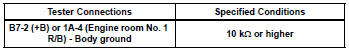
- Inspect the efi main relay.
- Measure the efi main relay resistance.
Standard resistance 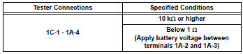
- Reinstall the integration relay.
- Check harness and connector (a/f sensor - efi relay)
- Check the efi no. 1 Fuse.
- Disconnect the b7 a/f sensor connector.
- Remove the integration relay from the engine room no. 1 Relay block.
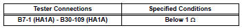
- Check the resistance.
Standard resistance (check for open)
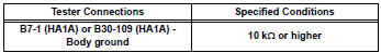
Standard resistance (check for short)
- Reconnect the a/f sensor connector.
- Reinstall the integration relay.
- Check harness and connector (a/f sensor - ecm)
- Disconnect the b7 a/f sensor connector.
- Disconnect the b30 ecm connector.
- Measure the resistance.
Standard resistance (check for open)
Standard resistance (check for short)
- Reconnect the a/f sensor connector.
- Reconnect the ecm connector.
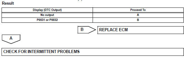
- Check whether dtc output recurs
- Connect the intelligent tester to the dlc3.
- Turn the ignition switch on.
- Turn the tester on.
- Clear dtcs (see page es-35).
- Start the engine.
- Allow the engine to idle for 1 minute or more.
- Select the following menu items: diagnosis / enhanced obd ii / dtc info / current codes.
- Read dtcs.
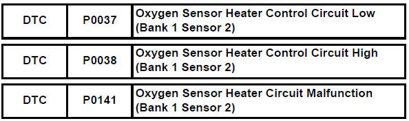
Oxygen sensor heater control circuit
Description
Refer to dtc p0136 (see page es-129).
Hint:
- When any of these dtcs are set, the ecm enters fail-safe mode. The ecm turns off the heated oxygen (ho2) sensor heater in fail-safe mode. Fail-safe mode continues until the ignition switch is turned off.
- The ecm provides a pulse width modulated control circuit to adjust the current through the heater. The ho2 sensor heater circuit uses a relay on the b+ side of the circuit.
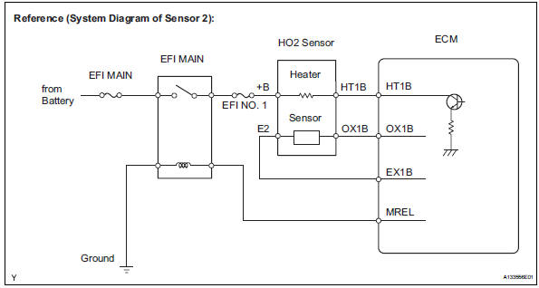
Monitor description
The sensing position of the heated oxygen (ho2) sensor has a zirconia element which is used to detect the oxygen concentration in the exhaust gas. If the zirconia element is at the appropriate temperature, and the difference between the oxygen concentrations surrounding the inside and outside surfaces of the sensor is large, the zirconia element generates voltage signals. In order to increase the oxygen concentration detecting capacity of the zirconia element, the ecm supplements the heat from the exhaust with heat from a heating element inside the sensor.
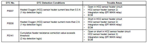
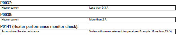
Heated oxygen sensor heater range check (p0037 and p0038): the ecm monitors the current applied to the o2 sensor heater to check the heater for malfunctions. If the current is below the threshold value, the ecm determines that there is an open circuit in the heater. If the current is above the threshold value, the ecm determines that there is a short circuit in the heater.
The ecm constantly monitors the current applied to the heater. If the ecm detects an open or short circuit, the ecm turns the mil on and sets a dtc.
If a malfunction is detected, the ecm cuts off the current applied to the heater.
Example: the ecm sets dtc p0038 when the current in the ho2 sensor heater is more than 2 a. Conversely, when the heater current is less than 0.3 A, dtc p0037 is set.
Heated oxygen sensor heater performance (p0141): after the accumulated heater on time exceeds 100 seconds, the ecm calculates the heater resistance using the battery voltage and the current applied to the heater.
If the resistance is above the threshold value, the ecm determines that there is a malfunction in the ho2 sensor heater and set dtc p0141.
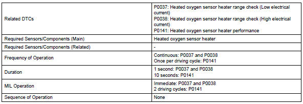
Monitor strategy
Typical enabling conditions
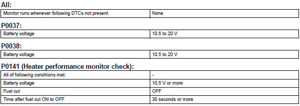
![]()
Typical malfunction thresholds
Component operating range
![]()
Wiring diagram
Refer to dtc p0136 (see page es-136).
Confirmation driving pattern
These dtcs are detected when the engine idles for 110 seconds or more.
Inspection procedure
Hint:
Sensor 2 refers to the sensor mounted behind the three-way catalytic converter (twc) and located far from the engine assembly.
Read freeze frame data using the intelligent tester. Freeze frame data records the engine condition when malfunctions are detected. When troubleshooting, freeze frame data can help determine if the vehicle was moving or stationary, if the engine was warmed up or not, if the air-fuel ratio was lean or rich, and other data from the time the malfunction occurred.
- Inspect heated oxygen sensor (heater resistance)
- Disconnect the b19 heated oxygen (ho2) sensor connector.
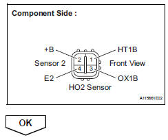
- Measure the resistance of the ho2 sensor connector.
Standard resistance 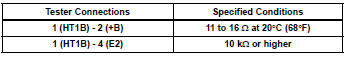
- Reconnect the ho2 sensor connector.
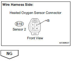
- Check terminal voltage (+b of ho2 sensor)
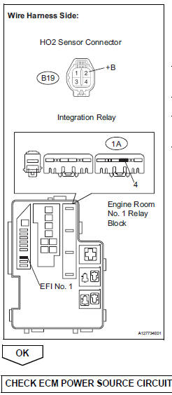
- Disconnect the b19 ho2 sensor connector.
- Turn the ignition switch on.
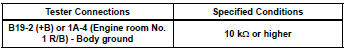
- Measure the voltage between the terminals of the b19 ho2 sensor connector and body ground.
Standard voltage 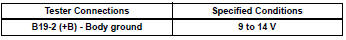
- Reconnect the ho2 sensor connector.
- Inspect integration relay (efi main relay) (see page es-84)


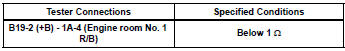
- Check harness and connector (ho2 sensor - efi relay)
- Check the efi no. 1 Fuse.
- Disconnect the b19 ho2 sensor connector.
- Remove the integration relay from the engine room no. 1 Relay block.
- Check the resistance.
Standard resistance (check for open)
Standard resistance (check for short)
- Reconnect the ho2 sensor connector.
- Reinstall the integration relay.
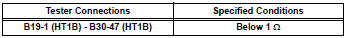
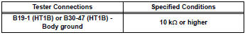
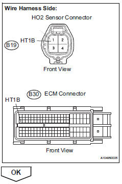
- Check harness and connector (ho2 sensor - ecm)
- Disconnect the b19 ho2 sensor connector.
- Disconnect the b30 ecm connector.
- Measure the resistance.
Standard resistance (check for open)
Standard resistance (check for short)
- Reconnect the ho2 sensor connector.
- Reconnect the ecm connector.
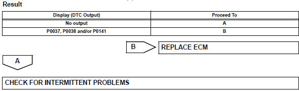
- Check whether dtc output recurs
- Connect the intelligent tester to the dlc3.
- Turn the ignition switch on.
- Turn the tester on.
- Clear dtcs (see page es-35).
- Start the engine.
- Allow the engine to idle for 2 minutes or more.
- Select the following menu items: diagnosis / enhanced obd ii / dtc info / current codes.
- Read dtcs.
 Camshaft position correlation (bank 1 sensor a)
Dtc P0016 P0016 crankshaft position - camshaft position correlation
(bank 1 sensor a)
Description
In the vvt (variable valve timing) system, the appropriate intake valve open
and close timing is
...
 Mass or volume air flow circuit
Description
The mass air flow (maf) meter is a sensor that measures the amount of air
flowing through the throttle
valve.
The ecm uses this information to determine the fuel injection time ...
Other materials:
Lumbar support adjuster assembly
Inspection
Inspect lumbar support adjuster assembl
Check operation of the lumbar support adjuster.
Check if the lumbar support adjuster moves
smoothly when the battery is connected to the
lumbar support adjuster motor connector
terminals.
Ok
If the result is not as spec ...
Problem symptoms table (2005/11-2006/01)
Hint:
Use the table below to help determine the cause of the
problem symptom. The potential causes of the symptoms are
listed in order of probability in the "suspected area" column of
the table. Check each symptom by checking the suspected
areas in the order they are listed. Replace p ...
Components
...
