Toyota RAV4 (XA40) 2013-2018 Service Manual: Rear axle hub bolt
Components
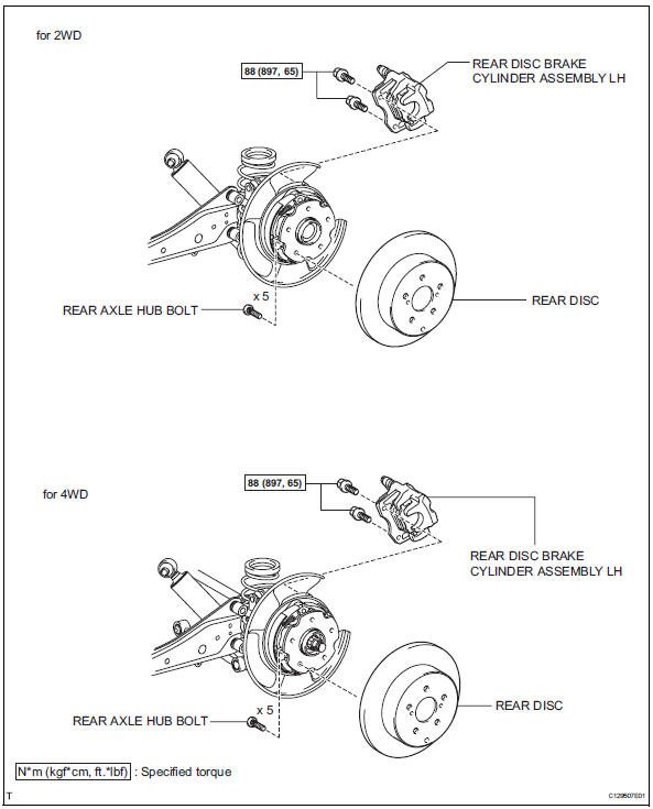
Replacement
Hint:
- Use the same procedures for the rh side and lh side.
- The procedures listed below are for the lh side.
- Remove rear wheel
- Remove rear disc brake cylinder assembly lh (see page br-55)
- Remove rear disc (see page br-57)
- Remove rear axle hub bolt
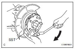
- Using sst and a brass bar or equivalent to hold the axle shaft, remove the hub bolt that needs to be replaced.
Sst 09650-17011
- Install rear axle hub bolt
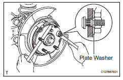
- Insert a new hub bolt into the bolt hole. Set a plate washer and nut on the hub bolt end.
- Using a brass bar or equivalent to hold the rear axle, install the hub bolt by tightening the nut. Then remove the nut and plate washer
- Install rear disc (see page br-58)
- Install rear disc brake cylinder assembly lh (see page br-61)
- Install rear wheel torque: 103 n*m (1,050 kgf*cm, 76 ft.*Lbf)
 Front axle hub
Components (2005/11-2006/01)
Components (2006/01- )
On-vehicle inspection
Check front axle hub bearing
Remove the front wheel.
Disconnect the front disc brake cylinder (see p ...
 Rear axle hub and bearing
Components
On-vehicle inspection
Remove rear wheel
Disconnect rear drive shaft assembly lh
(for 4wd)
Disconnect the drive shaft (see page ds-69).
Remove rear disc brake cy ...
Other materials:
Seat belt instructions
for canadian owners
(in french)
The following is a french explanation of seat belt instructions
extracted from the seat belt section in this manual.
See the seat belt section for more detailed seat belt instructions in
english.
Utilisation adéquate des ceintures de sécurité
Tirez sur la ceinture &eacut ...
Problem symptoms table (2005/11-2006/01)
Hint:
Use the table below to help determine the cause of the
problem symptom. The potential causes of the symptoms
are listed in order of probability in the "suspected area"
column of the table. Check each symptom by checking the
suspected areas in the order they are listed. Re ...
Ecm communication stop mode (2005/11-2006/01)
Description
Wiring diagram
Inspection procedure
Notice:
Turn the ignition switch off before measuring the resistances of the
main wire and the branch
wire.
After the ignition switch is turned off, check that the key reminder
warning system and light
reminder warning system ...
