Toyota RAV4 (XA50) 2019-2026 Owners Manual: Cargo and luggage
Take notice of the following information about storage precautions, cargo capacity and load.
WARNING
â– Things that must not be carried in the luggage compartment
The following things may cause a fire if loaded in the luggage compartment:
- Receptacles containing gasoline
- Aerosol cans
â– Storage precautions
Observe the following precautions.
Failure to do so may prevent the pedals from being depressed properly, may block the driver's vision, or may result in items hitting the driver or passengers, possibly causing an accident.
- Stow cargo and luggage in the luggage compartment whenever possible.
- Do not stack anything in the luggage compartment higher than the seatbacks.
- Do not place cargo or luggage in or on the following locations.
- At the feet of the driver
- On the front passenger or rear seats (when stacking items)
- On the luggage cover (if equipped)
- On the instrument panel
- On the dashboard
- Secure all items in the occupant compartment.
- When you fold down the rear seats, long items should not be placed directly behind the front seats.
- Never allow anyone to ride in
the luggage compartment. It is
not designed for passengers.
They should ride in their seats with their seat belts properly fastened. Otherwise, they are much more likely to suffer death or serious bodily injury, in the event of sudden braking, sudden swerving or an accident.
Capacity and distribution
Cargo capacity depends on the total weight of the occupants.
(Cargo capacity) = (Total load capacity) - (Total weight of occupants)
Steps for Determining Correct Load Limit -
(1) Locate the statement "The combined weight of occupants and cargo should never exceed XXX kg or XXX lbs." on your vehicle's placard.
(2) Determine the combined weight of the driver and passengers that will be riding in your vehicle.
(3) Subtract the combined weight of the driver and passengers from XXX kg or XXX lbs.
(4) The resulting figure equals the available amount of cargo and luggage load capacity.
For example, if the "XXX" amount equals 1400 lbs. and there will be five 150 lb passengers in your vehicle, the amount of available cargo and luggage load capacity is 650 lbs. (1400 - 750 (5 x 150) = 650 lbs.)
(5) Determine the combined weight of luggage and cargo being loaded on the vehicle.
That weight may not safely exceed the available cargo and luggage load capacity calculated in Step 4.
(6) If your vehicle will be towing a trailer, load from your trailer will be transferred to your vehicle.
Consult this manual to determine how this reduces the available cargo and luggage load capacity of your vehicle.
WARNING
â– Capacity and distribution
- Do not exceed the maximum axle weight rating or the total vehicle weight rating.
- Even if the total load of occupant' weight and the cargo load is less than the total load capacity, do not apply the load unevenly. Improper loading may cause deterioration of steering or braking control which may cause death or serious injury.
Calculation formula for your vehicle
- Cargo capacity
- Total load capacity (vehicle capacity weight)
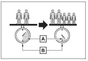
When 2 people with the combined weight of A lb. (kg) are riding in your vehicle, which has a total load capacity (vehicle capacity weight) of B lb. (kg), the available amount of cargo and luggage load capacity will be C lb. (kg) as follows:
B*2 lb. (kg) - A*1 lb. (kg) = C*3 lb. (kg)
*1:A = Weight of people *2:B = Total load capacity *3:C = Available cargo and luggage load
In this condition, if 3 more passengers with the combined weight of D lb. (kg) get on, the available cargo and luggage load will be reduced E lb. (kg) as follows:
C lb. (kg) - D*4 lb. (kg) = E*5 lb. (kg)
*4:D = Additional weight of people *5:E = Available cargo and luggage load
As shown in the example above, if the number of occupants increases, the cargo and luggage load will be reduced by an amount that equals the increased weight due to the additional occupants. In other words, if an increase in the number of occupants causes an excess of the total load capacity (combined weight of occupants plus cargo and luggage load), you must reduce the cargo and luggage on your vehicle.
WARNING
â– When loading cargo on the roof luggage carrier (if equipped)
Observe the following precautions:
- Place the cargo so that its weight is distributed evenly between the front and rear axles.
- If loading long or wide cargo, never exceed the vehicle overall length or width.
- Before driving, make sure the cargo is securely fastened on the roof luggage carrier.
- Loading cargo on the roof luggage carrier will make the center of gravity of the vehicle higher. Avoid high speeds, sudden starts, sharp turns, sudden braking or abrupt maneuvers, otherwise it may result in loss of control or vehicle rollover due to failure to operate this vehicle correctly and result in death or serious injury.
- If driving for a long distance, on rough roads, or at high speeds, stop the vehicle now and then during the trip to make sure the cargo remains in its place.
- Do not exceed 176.4 lb. (80 kg) cargo weight on the roof luggage carrier.
NOTICE
â– When loading cargo on the roof luggage carrier (if equipped)
Be careful not to scratch the surface of the moon roof (if equipped) or the panoramic moon roof (if equipped).
 Driving the vehicle
The following procedures
should be observed to
ensure safe driving:
Driving procedure
â– Driving
1. With the brake pedal
depressed, shift the shift
lever to D.
2. Release the parking brake.
If the p ...
 Vehicle load limits
Vehicle load limits include
total load capacity, seating
capacity, TWR (Trailer
Weight Rating) and cargo
capacity.
Total load capacity (vehicle
capacity weight):
Total load capacity means the
co ...
Other materials:
Heated steering wheel/seat
heaters/seat ventilators
Heated steering wheel
Warm up the grip of the steering
wheel
Seat heaters
Warm up the seat upholstery
Seat ventilators
Maintain good ventilation by
pulling air through the seat
upholstery
WARNING
â– To prevent minor burn injuries
Care should be taken if anyone in
the following categories ...
Trailer towing tips
Your vehicle will handle differently
when towing a trailer. Help
to avoid an accident, death or
serious injury, keep the following
in mind when towing:
Speed limits for towing a
trailer vary by state or province.
Do not exceed the
posted towing speed limit.
Toyota recommends that the
vehicle- ...
Ambient temperature sensor circuit
Description
The ambient temperature sensor is installed in the front part of the
condenser to detect the ambient
temperature and control the air conditioner. The sensor is connected to the
combination meter and
detects fluctuations in the ambient temperature. This data is used for
contr ...
