Toyota RAV4 (XA50) 2019-2026 Owners Manual: Heated steering wheel/seat heaters/seat ventilators
- Heated steering wheel Warm up the grip of the steering wheel
- Seat heaters
Warm up the seat upholstery - Seat ventilators Maintain good ventilation by pulling air through the seat upholstery
WARNING
â– To prevent minor burn injuries
Care should be taken if anyone in the following categories comes in contact with the steering wheel or seats when the heater is on:
- Babies, small children, the elderly, the sick and the physically challenged
- Persons with sensitive skin
- Persons who are fatigued
- Persons who have taken alcohol or drugs that induce sleep (sleeping drugs, cold remedies, etc.)
NOTICE
â– To prevent damage to the seat heaters and seat ventilators
Do not put heavy objects that have an uneven surface on the seat and do not stick sharp objects (needles, nails, etc.) into the seat.
â– To prevent battery discharge
Do not use the functions when the engine is not running.
Heated steering wheel
Turns the heated steering wheel on/off The indicator light comes on when the heated steering wheel is operating.
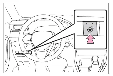
â– Operation condition
The engine switch is in ON.
Operating the seat heaters
Front
Turns the seat heaters on/off
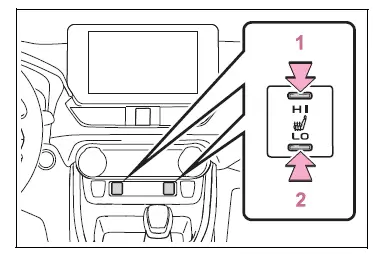
- High temperature
- Low temperature
When the seat heater is on, the indicator illuminates on the seat heater switch.
When not in use, put the switch in the neutral position. The indicator will turn off.
Rear
Turns the seat heaters on/off The indicator light comes on when the seat heater is operating.
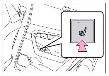
â– Operation condition
The engine switch is in ON.
WARNING
â– To prevent causes of overheating and minor burn injuries
Observe the following precautions when using a seat heater:
- Do not cover the seat with a blanket or cushion when using the seat heater.
- Do not use seat heater more than necessary.
Seat heaters and ventilators
Turns the seat heaters and ventilators on/off
The level indicators A come on during operation.
Each time the switch is pressed, the operation condition changes as follows.
Hi (3 segments lit)  Mid (2
segments
lit)  Lo (1 segment lit)
 Off
Off
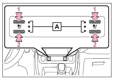
- Turns the seat heater on The level indicators A come on yellow during operation.
- Turns the seat ventilator on The level indicators A come on green during operation.
â– Operation condition
The engine switch is in ON.
â– Air conditioning system-linked control mode
When a seat ventilator is set to Hi, the fan speed of the seat ventilator may increase according to the fan speed of the air conditioning system.
WARNING
â– To prevent causes of overheating and minor burn injuries
Observe the following precautions when using a seat heater:
- Do not cover the seat with a blanket or cushion when using the seat heater.
- Do not use seat heater more than necessary.
 Front seat concentrated
airflow mode (S-FLOW)
Front seat concentrated
airflow mode (S-FLOW)
This function automatically controls
the air conditioning airflow
so that priority is given to the
front seats. Unnecessary air
conditioning is suppressed, contributing
to increased fuel efficiency.
...

Other materials:
If the electronic key does
not operate properly (vehicles
with smart key system)
If communication between
the electronic key and vehicle
is interrupted or the electronic key cannot
be used because the battery
is depleted, the smart key
system and wireless remote
control cannot be used. In
such cases, the doors can
be opened and the engine
can be started by following
the procedur ...
Replacement
Replace generator drive end frame bearing
Remove the 4 screws and bearing retainer.
Using sst and a hammer, tap out the bearing.
Sst 09950-60010 (09951-00250), 09950-70010
(09951-07100)
Using sst and a press, press in a new bearing.
Sst 09950-60010 (09951-00250), 09 ...
Front wiper motor
Inspection
Inspect front wiper motor
Check the lo operation.
Connect the battery's positive (+) lead to
terminal 5 (+1) and the negative (-) lead to
terminal 4 (e), and check that the front wiper
motor operates at low speed (lo).
Ok:
front wiper motor operates at low sp ...
