Toyota RAV4 (XA40) 2013-2018 Service Manual: Ambient temperature sensor circuit
![]()
Description
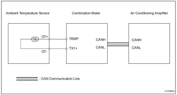
The ambient temperature sensor is installed in the front part of the condenser to detect the ambient temperature and control the air conditioner. The sensor is connected to the combination meter and detects fluctuations in the ambient temperature. This data is used for controlling the room temperature.
The sensor sends a signal to the air conditioning amplifier via the combination meter. The resistance of the ambient temperature sensor changes in accordance with the ambient temperature. As the temperature decreases, the resistance increases. As the temperature increases, the resistance decreases.
The air conditioning amplifier applies a voltage (5 v) to the ambient temperature sensor and reads voltage changes as changes in the resistance of the ambient temperature sensor. The combination meter sends the read signal to the air conditioning amplifier via can communication.
Wiring diagram
Inspection procedure
- Read value of intelligent tester (ambi temp sens)
- Connect the intelligent tester (with can vim) to the dlc3.
- Turn the ignition switch on and turn the intelligent tester main switch on.
- Select the item below in the data list, and read the value displayed on the intelligent tester.
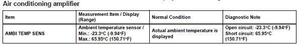
Ok: the display is as specified in the normal condition column.

- Inspect ambient temperature sensor
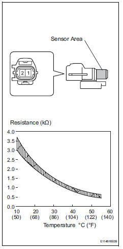
- Remove the ambient temperature sensor.
- Measure the resistance of the sensor.
Standard resistance 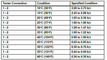
Notice:
- Touching the sensor even slightly may change the resistance value. Be sure to hold the connector of the sensor.
- When measuring, the sensor temperature must be the same as the ambient temperature.
Hint:
As the temperature increases, the resistance decreases (see the graph).

- Check wire harness (ambient temperature sensor - combination meter)
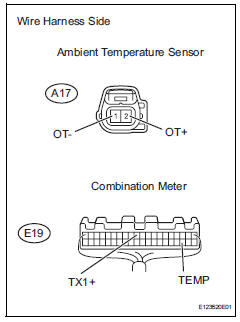
- Disconnect the a17 sensor connector.
- Disconnect the e19 meter connector.
- Measure the resistance of the wire harness side connectors.
Standard resistance 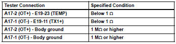

Replace combination meter
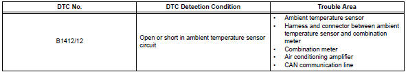
 Diagnostic trouble code chart (2006/01- )
Hint:
When the air conditioning system functions properly, dtc
b1400/00 is output.
Hint:
*1: Dtc b1422/22 (compressor lock sensor circuit) is
indicated only for a currently occurring malfunct ...
 Evaporator temperature sensor circuit
Description
The no. 1 Cooler thermistor (evaporator temperature sensor) is installed on
the evaporator in the air
conditioning unit to detect the temperature of the cooled air that has passed ...
Other materials:
Installation
Hint:
When installing the spoiler, heat the vehicle body and
spoiler using a heat light.
Standard heating temperature
Notice:
Do not heat the body and spoiler excessively.
Install center stop light
Install the center stop light with the 2 screws.
Install rear spoiler
...
Illumination circuit
Description
The main body ecu receives information regarding the door courtesy switch and
door lock position
switch, and turns on the room light.
Wiring diagram
Inspection procedure
Perform active test by intelligent tester (main body ecu)
Connect the intelligent tester (with can ...
Installation
Hint:
Use the same procedures for the lh side and rh side.
The procedures listed below are for the lh side.
A bolt without a torque specification is shown in the
standard bolt chart (see page ss-2).
Install rear no. 1 Seat outer belt assembly lh
Align the claws with the sea ...
