Toyota RAV4 (XA40) 2013-2018 Service Manual: Diagnosis system
- Description
Power door lock control system data can be read in the data link connector 3 (dlc3) of the vehicle. When the system seems to be malfunctioning, use the intelligent tester to check for malfunctions and perform repairs.
- Check dlc3
- The ecu uses iso 15765-4 for communication.
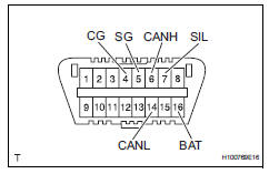
The terminal arrangement of the dlc3 complies with iso 15031-3 and matches the iso 15765-4 format.
Notice:
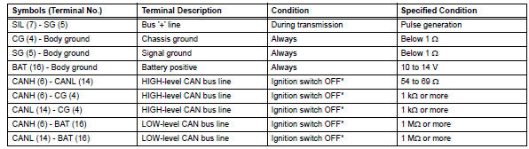
*: Before measuring the resistance, leave the vehicle for at least 1 minute and do not operate the ignition switch, any switches or doors.
If the result is not as specified, the dlc3 may have a malfunction. Repair or replace the harness and connector.
Hint:
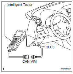
Connect the cable of the intelligent tester to the dlc3, turn the ignition switch on and attempt to use the tester. If the display indicates that a communication error has occurred, there is a problem either with the vehicle or with the tester.
- If communication is normal when the tester is connected to another vehicle, inspect the dlc3 of the original vehicle.
- If communication is still not possible when the tester is connected to another vehicle, the problem may be in the tester itself. Consult the service department listed in the tester's instruction manual.
 Terminals of ecu
Check instrument panel junction block (main body ecu)
Disconnect the ib and ie junction block connectors.
Measure the voltage and resistance of the wire
harness side connectors.
...
 Data list / active test
Read data list
Hint:
Using the intelligent tester's data list allows switch,
sensor, actuator and other item values to be read without
removing any parts. Reading the data list early in
trou ...
Other materials:
Components
...
Correct use of the seat
belts
Extend the shoulder belt so
that it comes fully over the
shoulder, but does not come
into contact with the neck or
slide off the shoulder.
Position the lap belt as low as
possible over the hips.
Adjust the position of the
seatback.
Sit up straight and well back
in the seat.
Do not twis ...
Problem symptoms table
When a "normal" code is output during a dtc check but
the problem is still occurring, use the problem symptoms
table. The suspected areas (circuits or parts) for each
problem symptom are in the table. The suspected areas
are listed in order of probability. A description of each of
the ...
