Toyota RAV4 (XA40) 2013-2018 Service Manual: Diagnosis system
- Description
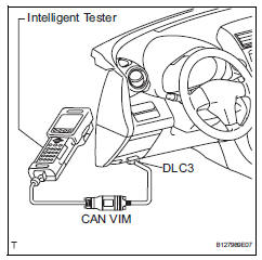
- Data of the system can be read through the data
link connector 3 (dlc3) of the vehicle.
Therefore, when the system seems to be malfunctioning, use the intelligent tester to check for a malfunction and repair it.
- Check dlc3
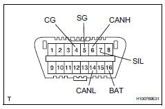
- The vehicle's ecm uses iso 15765-4 communication protocol. The terminal arrangement of the dlc3 complies with sae j1962 and matches the iso 15765-4 format.
Hint:
Connect the cable of the intelligent tester to the dlc3, turn the ignition switch on and attempt to use the tester. If the display indicates that a communication error has occurred, there is a problem either with the vehicle or with the tester.
- If communication is normal when the tester is connected to another vehicle, inspect the dlc3 of the original vehicle.
- If communication is still not possible when the tester is connected to another vehicle, the problem may be in the tester itself. Consult the service department listed in the tester's instruction manual.
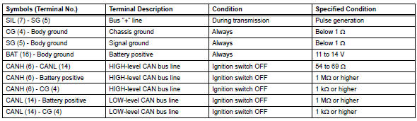
 Terminals of ecu
Check combination meter assembly
Disconnect the e19 meter connector.
Measure the voltage and resistance of the wire
harness side connector.
If the result is not as specifie ...
 Data list / active test
Active test
Hint:
Performing the intelligent tester active test allows
relay, vsv, actuator and other items to be operated
without removing any parts. Performing the active
test early in tro ...
Other materials:
Bus ic communication malfunction
Description
The air conditioning harness connects the air conditioning amplifier and the
servos. The air conditioning
amplifier supplies power and sends operation instructions to each servo through
the air conditioning
harness. Each servo sends damper position information to the air condi ...
Reassembly
Install front oil pump oil seal
Using sst and a hammer, install a new oil seal to
the pump.
Sst 09350-32014 (09351-32140)
Hint:
The seal end should be flat with the outer edge of
the oil pump.
Coat the lip of the oil seal with petroleum jelly.
Install front oil pump bo ...
Installation
Notice:
Do not heat the vehicle body, emblem and name plate
excessively.
Hint:
When installing the emblem and name plate, heat the vehicle
body, emblem and name plate using a heat light.
Standard heating temperature
Install no. 4 Back door name plate (for 4wd)
Clean the vehicle body ...
