Toyota RAV4 (XA40) 2013-2018 Service Manual: License plate light assembly
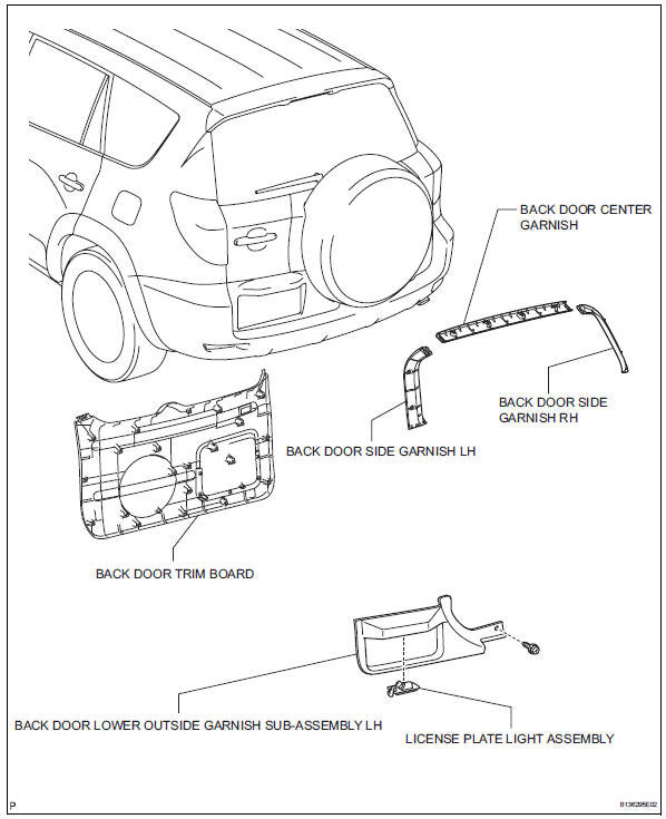
Components
Removal
- Disconnect cable from negative battery terminal
Caution:
Wait at least 90 seconds after disconnecting the cable from the negative (-) battery terminal to prevent airbag and seat belt pretensioner activation.
- Remove back door center garnish (see page ed-59)
- Remove back door side garnish lh (see page ed-59)
- Remove back door side garnish rh (see page ed-59)
- Remove back door trim board (see page ed- 59)
- Remove back door lower outside garnish sub-assembly lh (see page et-60)
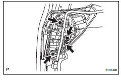
- Remove license plate light assembly
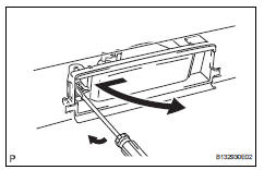
- Disconnect the connector.
- Using a screwdriver, remove the light as shown in the illustration.
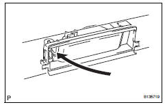
Disassembly
- Remove license plate light bulb
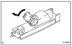
- Turn the bulb/socket unit in the direction indicated by the arrow and pull to remove it.
- Remove the bulb from the socket.
Reassembly
- Install license plate light bulb

- Install the bulb to the socket.
- Insert the bulb/socket unit into the headlight.
- Turn the bulb/socket unit in the direction indicated by the arrow to install it.
Installation
Hint:
- Use the same procedures for the rh and lh sides.
- The procedures listed below are for the lh side.
- Install rear combination light assembly
- Attach the clip to install the light.
- Install the 3 nuts and connect the connector.
- Connect cable to negative battery terminal
Installation
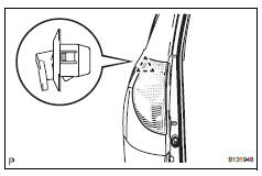
- Install license plate light assembly
- Install the light as shown in the illustration.
- Install back door lower outside garnish sub-assembly (see page et-61)
- Install back door trim board (see page ed- 66)
- Install back door side garnish rh (see page ed-67)
- Install back door side garnish lh (see page ed-67)
- Install back door center garnish (see page ed-67)
- Connect cable to negative battery terminal
 Rear combination light assembly
Components
Removal
Hint:
Use the same procedures for the rh and lh sides.
The procedures listed below are for the lh side.
Disconnect cable from negative battery
terminal
Cautio ...
 High mounted stop light assembly
Components
Removal
Disconnect cable from negative battery
terminal
Caution:
Wait at least 90 seconds after disconnecting the
cable from the negative (-) battery terminal to
prevent ai ...
Other materials:
Freeze frame data
Freeze frame data
Hint:
Whenever a dtc is detected or the abs operates,
the skid control ecu stores the current vehicle
(sensor) state as freeze frame data.
The skid control ecu stores the number of times
(maximum: 31) the ignition switch has been turned
from off to on since the ...
Removal
(2006/01- )
Remove front wheel
Drain automatic transaxle fluid
Drain the automatic transaxle fluid for u140f (see
page ax-147).
Drain the automatic transaxle fluid for u241e (see
page ax-146).
Drain the automatic transaxle fluid for u151f (see
page ax-173).
Remove front axle hub nut ( ...
Vanity light
Components
Removal
Hint:
Use the same procedures for the rh and lh sides.
The procedures listed below are for the lh side.
Disconnect cable from negative battery
terminal
Caution:
Wait at least 90 seconds after disconnecting the
cable from the negative (-) battery terminal t ...
