Toyota RAV4 (XA40) 2013-2018 Service Manual: High mounted stop light assembly
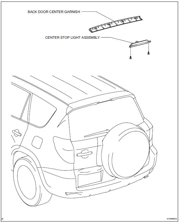
Components
Removal
- Disconnect cable from negative battery terminal
Caution:
Wait at least 90 seconds after disconnecting the cable from the negative (-) battery terminal to prevent airbag and seat belt pretensioner activation.
- Remove back door center garnish (see page ed-59)
- Remove center stop light assembly
- Disconnect the connector.
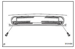
- Remove the 2 screws and center stop light.
Installation
- Install center stop light assembly
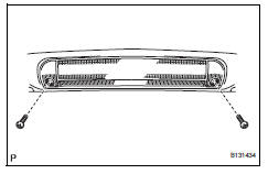
- Install the center stop light with the 2 screws.
- Connect the connector.
- Install back door center garnish (see page ed-67)
- Connect cable to negative battery terminal
 License plate light assembly
Components
Removal
Disconnect cable from negative battery
terminal
Caution:
Wait at least 90 seconds after disconnecting the
cable from the negative (-) battery terminal to
prevent ai ...
 Map light assembly
Components
Removal
Disconnect cable from negative battery
terminal
Caution:
Wait at least 90 seconds after disconnecting the
cable from the negative (-) battery terminal to
prevent ai ...
Other materials:
Registration
In case of tire pressure warning ecu
replacement
Read id stored in the old ecu using the intelligent
tester.
In case of tire pressure warning valve and
transmitter and/or tire pressure warning
ecu replacement
Read the id written on the tire pressure monitor
valve.
...
Open in one side of can branch line
Description
If 2 or more ecus and/or sensors do not appear on the intelligent tester's
"bus check" screen via the
can vim, one side of the can branch wire may be open. (One side of the canh
[branch wire] /canl
[branch wire] of the ecu and/or sensor is open.)
Wiring diagram
...
Data list
Hint:
By reading the data list displayed on an intelligent
tester, values can be checked, including those of the
switches, sensors, and actuators, without removing any
parts. Reading the data list as the first step of
troubleshooting is one method of shortening diagnostic
time.
Notice:
In th ...
