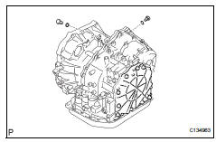
Toyota RAV4 (XA40) 2013-2018 Service Manual: Disassembly
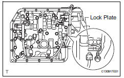
- Remove park/neutral position switch assembly
- Remove the nut, washer and control shaft lever.
- Using a screwdriver, pry off the lock plate.
- Remove the nut and lock plate.
- Remove the 2 bolts and pull out the switch.
- Remove breather plug hose
- Remove oil cooler outlet tube union
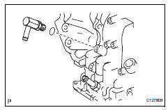
- Remove the union.
- Remove the o-ring from the union.
- Remove oil cooler inlet tube union
- Remove the union.
- Remove the o-ring from the union.
- Remove speed sensor
- Remove the 2 bolts and 2 transmission revolution sensors from the transaxle.
- Remove the 2 o-rings from the sensors.
- Remove no. 1 Transaxle case plug
- Remove the 4 plugs from the transaxle.
- Remove the 4 o-rings from the 4 plugs.
- Place transaxle on wooden blocks
- Remove automatic transaxle oil pan subassembly
- Remove the 18 bolts.
- Remove the oil pan and 3 magnets.
- Remove the gasket from the oil pan.
- Inspect automatic transaxle oil pan subassembly (see page ax-184)
- Remove valve body oil strainer assembly
- Remove the 3 bolts and oil strainer.
- Remove the o-ring from the oil strainer.
- Remove transmission wire
- Disconnect the 5 shift solenoid valve connectors.
- Remove the bolt, lock plate and atf temperature sensor.
- Remove the bolt and transaxle wire.
- Remove the o-ring from the transaxle wire.
- Remove transmission valve body assembly
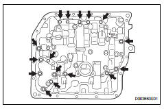
- Support the valve body and remove the 17 bolts and valve body.
- Remove no. 1 Governor apply gasket
- Remove the governor apply gasket from the transaxle case.
- Remove transaxle case 2nd brake gasket
- Remove the 2nd brake gasket from the transaxle.
- Remove brake drum gasket
- Remove the brake drum gasket from the transaxle.
- Remove check ball body
- Remove the check ball and spring from the transaxle.
- Remove c-3 accumulator piston
- Remove the spring from the c-3 accumulator piston.
- Apply compressed air (392 kpa, 4.0 Kgf/cm2, 57 psi) to the oil hole and remove the c-3 accumulator piston.
Notice:
- Applying compressed air may cause the piston to jump out. When removing the piston, hold it with your hand using a waste cloth.
- Make sure not to spatter atf when applying compressed air.
- Remove the o-ring from the c-3 accumulator piston.
- Remove c-1 accumulator piston
- Apply compressed air (392 kpa, 4.0 Kgf/cm2, 57 psi) to the oil hole and remove the c-1 accumulator piston and spring.
Notice:
- Applying compressed air may cause the piston to jump out. When removing the piston, hold it with your hand using a waste cloth.
- Make sure not to spatter atf when applying compressed air.
- Remove the 2 o-rings from the c-1 accumulator piston.
- Remove b-3 accumulator piston
- Apply compressed air (392 kpa, 4.0 Kgf/cm2, 57 psi) to the oil hole and remove the b-3 accumulator piston and 2 springs.
Notice:
- Applying compressed air may cause the piston to jump out. When removing the piston, hold it with your hand using a waste cloth.
- Make sure not to spatter atf when applying compressed air.
- Remove the o-ring from the b-3 accumulator piston.
- Remove manual detent spring subassembly
- Remove the 2 bolts, manual detent spring and cover.
- Remove parking lock pawl bracket
- Remove the 2 bolts and parking lock pawl bracket.
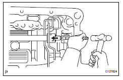
- Remove manual valve lever shaft retainer spring
- Using needle-nose pliers, remove the retainer spring.
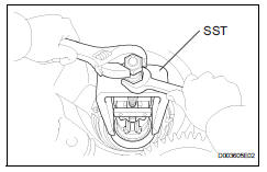
- Remove manual valve lever sub-assembly
- Using a chisel and hammer, unstake and remove the spacer.
- Using a pin punch and hammer, tap out the pin.
Hint:
Slowly tap out the pin so that it will not fall into the transaxle.
- Remove the manual valve lever shaft and manual valve lever.
- Remove parking lock rod sub-assembly
- Remove the parking lock rod from the manual valve lever.
- Remove manual valve lever shaft oil seal
- using a screwdriver, pry out the oil seal from the transaxle.
- Fix automatic transaxle assembly
- Fix the transaxle case with the oil pump side facing up.
- Inspect input shaft end play (see page ax- 184)
- Remove no. 1 Transaxle case plug
- Remove the 2 plugs.
- Remove the 2 o-rings from the 2 plugs.
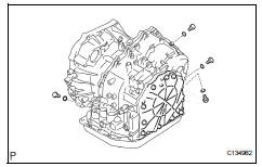
- Remove transaxle housing
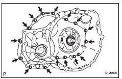
- Remove the 16 bolts.
- Tap on the circumference of the transaxle housing with a plastic-faced hammer to remove the transaxle housing from the transaxle case.
Notice:
The differential may be accidentally removed when the transaxle housing is removed.
- Remove oil pump assembly
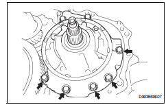
- Remove the 7 bolts and oil pump from the transaxle.
- Remove thrust needle roller bearing
- Remove thrust needle roller bearing from the underdrive planetary gear.
- Remove no. 2 Thrust bearing underdrive race
- Remove the thrust bearing underdrive race from the underdrive planetary gear.
- Remove differential gear assembly
- Remove the differential gear form the transaxle.
- Remove overdrive brake gasket
- Remove the 2 overdrive brake gaskets from the transaxle.
- Remove forward clutch assembly
- Remove the forward clutch from the transaxle.
- Remove the thrust bearing from the forward clutch.
- Remove multiple disc clutch hub
- Remove the thrust bearing, multiple clutch hub, needle roller bearing and bearing race from the transaxle.
- Inspect multiple disc clutch hub (see page ax-184)
- Remove underdrive planetary gear assembly
- Remove the bolt and parking pawl shaft clamp.
- Remove the parking lock pawl shaft.
- Push the parking lock pawl.
Hint:
Failure to do so will cause interference when the underdrive planetary gear is removed.
- Remove the underdrive planetary gear from the transaxle.
Notice:
Be careful so that the underdrive planetary gear assembly will not fall out.
- Remove the spring, pawl pin and parking lock pawl.
- Remove underdrive clutch assembly
- Remove the underdrive clutch, thrust bearing and bearing race from the transaxle.
- Remove underdrive 1-way clutch assembly
- Using a screwdriver, pry out the snap ring from the transaxle.
- Remove the 1-way clutch from the transaxle.
- Remove the outer race retainer from the 1-way clutch.
- Remove no. 2 Underdrive clutch disc
- Using a screwdriver, pry out the snap ring.
- Remove the flange, 3 discs and 3 plates from the transaxle.
- Inspect no. 2 Underdrive clutch disc (see page ax-185)
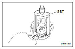
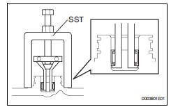
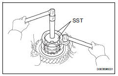
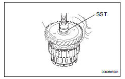
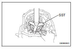
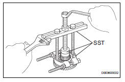
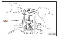
- Remove underdrive brake return spring sub-assembly
- Using sst, a snap ring expander and press, remove the snap ring and piston return spring.
Sst 09387-00020
- Inspect underdrive brake return spring sub-assembly (see page ax-185)
- Remove no. 1 Transaxle case plug
- Remove the 2 plugs from the transaxle rear cover.
- Remove the 2 o-rings from the 2 plugs.
- Remove transaxle rear cover subassembly
- Remove the 11 bolts.
- Tap in the circumference of the rear cover with a plastic-fased hammer to remove the transaxle rear cover from the transaxle.
- Remove the 2 oil seal rings from the transaxle rear cover.
- Using a t30 ''torx'' socket wrench, remove the 2 screws and transaxle rear cover plate.
- Using sst, remove the needle-roller bearing from the transaxle rear cover.
Sst 09387-00041 (09387-01040, 09387-01010, 09387-01030)
- Remove brake apply tube
- Remove the bolt, clamp and 2 brake apply tubes.
- Remove the brake apply tube from the clamp.
- Remove front clutch apply tube
- Remove the front clutch apply tube from the clamp.
- Remove no. 1 Governor apply gasket
- Using a screwdriver, remove the 2 apply gaskets.
- Remove direct clutch assembly
- Remove the thrust bearing and direct clutch from the transaxle.
- Remove the bearing race from the direct clutch.
- Remove rear planetary sun gear assembly
- Remove the rear planetary sun gear from the transaxle.
- Remove the thrust bearing from the rear planetary sun gear.
- Remove the no. 1 Thrust washer from the rear planetary sun gear.
- Remove 1-way clutch assembly
- Remove the 1-way clutch and thrust bearing from the transaxle.
- Remove the inner race from the 1-way clutch.
- Remove 1-way clutch outer sleeve
- Remove 2nd brake clutch disc
- Using a screwdriver, remove the snap ring.
- Remove the flange, 3 discs and 3 plates from the transaxle.
- Inspect 2nd brake clutch disc (see page ax- 185)
- Remove 2nd brake piston assembly
- Using a screwdriver, remove the snap ring.
- Remove the 2nd brake piston from the transaxle.
- Remove rear planetary gear assembly
- Using a screwdriver, pry out the snap ring.
- Remove the rear planetary gear from the transaxle.
- Remove the no. 1 Planetary carrier thrust washer from the rear planetary gear.
- Remove the bearing race from the rear planetary gear.
- Remove input sun gear
- Remove the 2 thrust bearings, bearing race and input sun gear from the transaxle.
- Remove front planetary gear assembly
- Using a chisel and hammer, unstake the lock washer.
Notice:
Push down all claws of the washer. Otherwise sst cannot be fully pressed against the nut and cannot loosen the nut.
- Using sst, remove the nut.
Sst 09387-00030, 09387-00080
- Using sst and a press, remove the front planetary gear from the counter drive gear.
Sst 09950-60010 (09951-00450)
- Remove the front planetary gear from the brake hub.
- Remove front planetary ring gear
- Using a screwdriver, remove the snap ring and front planetary ring gear from the brake hub.
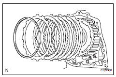
- Remove 1st and reverse brake clutch disc
- Remove the flange, 5 discs and 5 plates from the transaxle case.
- Inspect 1st and reverse brake clutch disc (see page ax-185)
- Remove 1st and reverse brake return spring sub-assembly
- Using sst, a press and snap ring expander, remove the snap ring and piston return spring.
Sst 09387-00070
Notice:
- Stop the press when the spring sheet is lowered 1 to 2 mm (0.039 To 0.078 In.) From the snap ring groove, preventing the spring sheet from deforming.
- Do not expand the snap ring excessively.
- Inspect 1st and reverse brake return spring sub-assembly (see page ax-186)
- Remove 1st and reverse brake piston
- Apply compressed air (392 kpa, 4.0 Kgf/cm2, 57 psi) to the transaxle case to remove the 1st and reverse brake piston.
Notice:
- Applying compressed air may cause the piston to jump out. When removing the piston, hold it with your hand using a waste cloth.
- Make sure not to spatter atf when applying compressed air.
- Remove the 2 o-rings from the 1st and reverse brake piston.
- Remove counter drive gear
- Using sst and a press, remove the counter drive gear from the transaxle case.
Sst 09950-60010 (09951-00580), 09950-70010 (09951-07100)
- As shown in the illustration, tighten the 2 bolts evenly and make a clearance of approximately 20.0 Mm (0.797 In.) Between the counter drive gear and the inner race.
- Using sst, remove the tapered roller bearing.
Sst 09950-60010 (09951-00580), 09950-00020, 09950-00030
- Using a brass bar and hammer, tap out the 2 bearing outer races.
- Remove counter drive gear hole snap ring
- Using a screwdriver, pry out the snap ring from the transaxle.
- Remove no. 2 Breather plug
- Remove underdrive brake piston
- Apply compressed air (392 kpa, 4.0 Kgf/cm2, 57 psi) to the transaxle case to remove the underdrive brake piston.
- Using sst, remove the needle-roller bearing from the transaxle
Sst 09387-00041 (09387-01010, 09387-01030, 09387-01040)
- Remove underdrive clutch drum oil seal ring
- Remove the 2 oil seal rings from the transaxle.
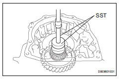
- Remove underdrive cylindrical roller bearing
- Using sst, remove the cylindrical roller bearing from the transaxle.
Sst 09514-35011
- Remove underdrive output shaft oil seal ring
- Remove the oil seal ring from the transaxle housing.
- Remove differential gear lube apply tube
- Remove the bolt, clamp and apply tube from the transaxle.
 Automatic transaxle unit
Components
...
 Inspection
Inspect automatic transaxle oil panel
sub-assembly
Remove the magnets and use them to collect any
steel chips. Examine the chips and particles in the
pan and on the magnet to determ ...
Other materials:
Vehicle information display
â– Drive information
2 items that are selected using
the "Drive Info Items" setting
(average speed, distance and total time) can be displayed vertically.
The displayed information
changes according to the "Drive
Info Type" setting (since the system
was started or between
resets).
Use the displayed ...
Child restraint system
â– Types of child restraint system installation methods
Confirm with the operation manual enclosed with the child restraint
system about the installation of the child restraint system.
Seat belt attachment
Child restraint LATCH
anchors attachment
Anchor brackets (for
top tether strap) attachment
...
Camshaft position "a" actuator circuit (bank 1)
Dtc P0010 Camshaft
position "a" actuator circuit (bank
1)
Description
The variable valve timing (vvt) system includes the ecm, ocv and vvt
controller. The ecm sends a
target duty-cycle control signal to the ocv. This control signal regulates the
oil pressure supplied to the ...
