Toyota RAV4 (XA40) 2013-2018 Service Manual: Compressor solenoid circuit (2006/01- )

Description
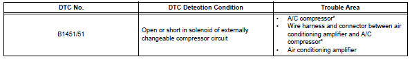
In this circuit, the compressor receives a refrigerant compression demand signal from the air conditioning amplifier. Based on this signal, the compressor changes the degree of refrigerant compression.
Hint:
*: Compressor and pulley for 2az-fe, compressor and magnetic clutch for 2gr-fe
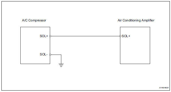
Wiring diagram
Inspection procedure
- Read value of intelligent tester (reg ctrl currnt)
- Connect the intelligent tester (with can vim) to the dlc3.
- Turn the ignition switch on and turn the intelligent tester main switch on.
- Select the items below in the data list, and read the value displayed on the intelligent tester.
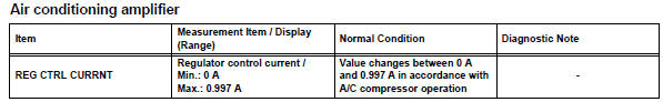
Ok: the display is as specified in the normal condition column.

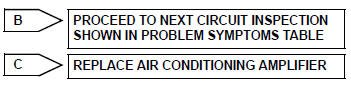
- Inspect a/c compressor
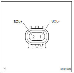
- Disconnect the a/c compressor clutch connector.
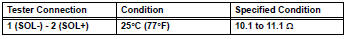
- Measure the resistance of the connector.
Standard resistance


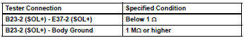
- Check wire harness (a/c compressor - air conditioning amplifier)
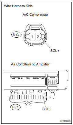
- Disconnect the b23 a/c compressor connector.
- Disconnect the e37 amplifier connector.
- Measure the resistance of the wire harness side connectors.
Standard resistance

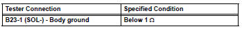
- Check wire harness (a/c compressor - body ground)
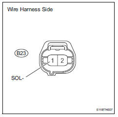
- Disconnect the b23 a/c compressor connector.
- Measure the resistance of the wire harness side connector.
Standard resistance

Replace air conditioning amplifier
 Compressor solenoid circuit (2005/11-2006/01)
Description
In this circuit, the compressor receives a refrigerant compression demand
signal from the air conditioning
amplifier. Based on this signal, the compressor changes the degree of
r ...
 Bus ic communication malfunction
Description
The air conditioning harness connects the air conditioning amplifier and the
servos. The air conditioning
amplifier supplies power and sends operation instructions to each servo th ...
Other materials:
Precaution
If any of following conditions are met,
keep engine idling with a/c on (engine
speed at less than 2000 rpm) for at least 1
minute:
Refrigerant gas has been refilled or a/c parts have
been replaced.
A long time has elapsed since the engine was
stopped.
Notice:
If the engine s ...
Check for intermittent problems
Hint:
Inspect the vehicle's ecm using check mode. Intermittent
problems are easier to detect with the intelligent tester when
the ecm is in check mode. In check mode, the ecm uses 1
trip detection logic, which is more sensitive to malfunctions
than normal mode (default), which uses 2 trip detec ...
Installation
Install camshaft position sensor
Notice:
Make sure that the o-ring is not cracked or jammed
when installing it.
Apply a light coat of engine oil to the o-ring of the
sensor.
Install the sensor with the bolt.
Torque: 9.0 N*m (90 kgf*cm, 80 in.*Lbf)
Connect the sensor co ...
