Toyota RAV4 (XA40) 2013-2018 Service Manual: Oxygen (a/f) sensor pumping current circuit
Description
Refer to dtc p2195 (see page es-292).
Monitor description
The air-fuel ratio (a/f) sensor varies its output voltage in proportion to the air-fuel ratio. If the a/f sensor impedance (alternating current resistance) or output voltage deviates greatly from the standard range, the ecm determines that there is an open or short in the a/f sensor circuit.
Monitor strategy
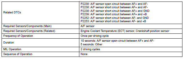
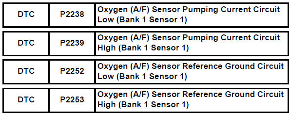
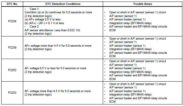
Typical enabling conditions
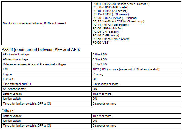
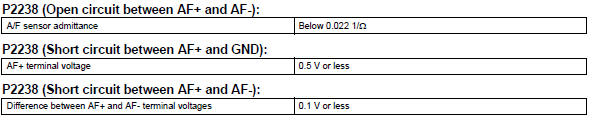
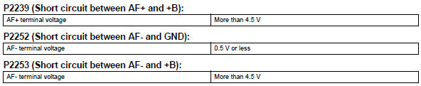
Typical malfunction thresholds
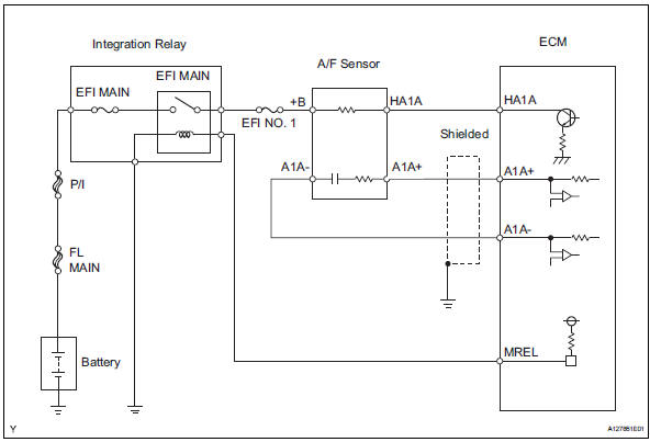
Wiring diagram
Inspection procedure
Hint:
- Although the dtc titles say oxygen sensor, these dtcs relate to the air-fuel ratio (a/f) sensor.
- Sensor 1 refers to the sensor mounted in front of the three-way catalytic converter (twc) and located near the engine assembly.
Hint:
Intelligent tester only: malfunctioning areas can be identified by performing the a/f control function provided in the active test. The a/f control function can help to determine whether the air-fuel ratio (a/f) sensor, heated oxygen (ho2) sensor and other potential trouble areas are malfunctioning.
The following instructions describe how to conduct the a/f control operation using the intelligent tester.
- Connect the intelligent tester to the dlc3.
- Start the engine and turn the tester on.
- Warm up the engine at an engine speed of 2,500 rpm for approximately 90 seconds.
- On the tester, select the following menu items: diagnosis / enhanced obd ii / active test / a/ f control.
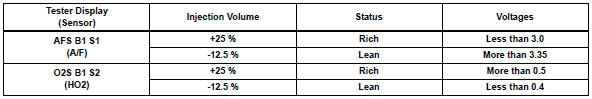
- Perform the a/f control operation with the engine idling (press the right or left button to change the fuel injection volume).
- Monitor the output voltages of the a/f and ho2 sensors (afs b1 s1 and o2s b1 s2) displayed on the tester.
Hint:
- The a/f control operation lowers the fuel injection volume by 12.5 % Or increases the injection volume by 25 %.
- The sensors react in accordance with increases and decreases in the fuel injection volume.
Standard
Notice:
The a/f sensor has an output delay of a few seconds and the ho2 sensor has a maximum output delay of approximately 20 seconds.
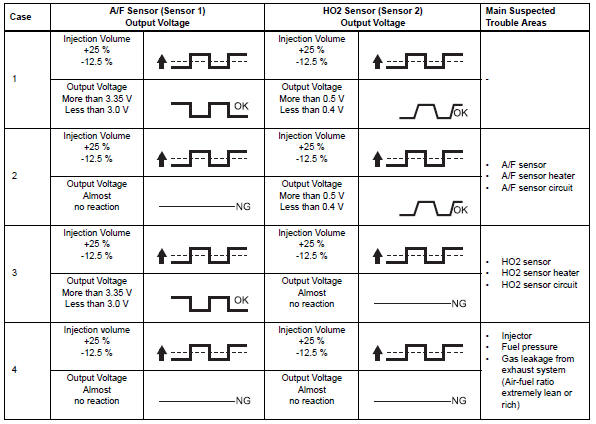
Following the a/f control procedure enables technicians to check and graph the output voltages of both the a/f and ho2 sensors.
To display the graph, select the following menu items on the tester: diagnosis / enhanced obd ii / active test / a/f control / user data / afs b1 s1 and o2s b1 s2; then press the yes button and then the enter button followed by the f4 button.
Hint:
Read freeze frame data using the intelligent tester. Freeze frame data records the engine condition when malfunctions are detected. When troubleshooting, freeze frame data can help determine if the vehicle was moving or stationary, if the engine was warmed up or not, if the air-fuel ratio was lean or rich, and other data from the time the malfunction occurred.
- Inspect air-fuel ratio sensor (heater resistance) (see page es-83)

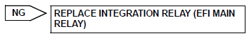
- Inspect integration relay (efi main relay) (see page es-84)

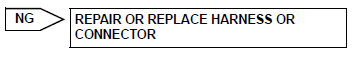
- Check harness and connector (a/f sensor - ecm) (see page es-310)

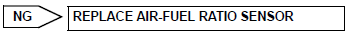
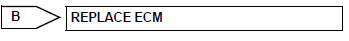
- Replace air-fuel ratio sensor

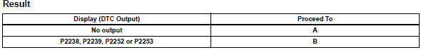
- Check whether dtc output recurs
- Connect the intelligent tester to the dlc3.
- Turn the ignition switch on and turn the tester on.
- Clear dtcs (see page es-35).
- Start the engine.
- Allow the engine to idle for 5 minutes or more.
- Select the following menu items: diagnosis / enhanced obd ii / dtc info / pending codes.
- Read pending dtcs.

 Oxygen (a/f) sensor signal stuck
Hint:
Although the dtc titles say oxygen sensor, these dtcs relate to the
air-fuel ratio (a/f) sensor.
Sensor 1 refers to the sensor mounted in front of the three-way
catalytic convert ...
 Evaporative emission leak detection pump
Dtc summary
Hint:
The leak detection pump is built into the canister pump module.
Description
The description can be found in the evap (evaporative emission) system (see
page es-335).
I ...
Other materials:
How to proceed with troubleshooting
Hint:
Use these procedures to troubleshoot the tire pressure
warning system.
*: Use the intelligent tester.
Vehicle brought to workshop
Inspect battery voltage
Standard voltage:
11 to 14 v
If the voltage is below 11 v, recharge or replace the battery
before proceeding.
...
How to proceed with troubleshooting
Hint:
Use these procedures to troubleshoot the vehicle stability
control system.
*: Use the intelligent tester.
Vehicle brought to workshop
Inspect battery voltage
Standard voltage:
11 to 14 v
If the voltage is below 11 v, recharge or replace the battery
before proceedin ...
Basic inspection
When a malfunction is not confirmed by the dtc check,
troubleshooting should be carried out in all circuits
considered to be possible causes of the problem. In many
cases, by carrying out the basic engine check shown in the
following flowchart, the location of the problem can be found
quickly a ...
