Toyota RAV4 (XA40) 2013-2018 Service Manual: Evaporative emission leak detection pump
Dtc summary
Hint:
The leak detection pump is built into the canister pump module.
Description
The description can be found in the evap (evaporative emission) system (see page es-335).
Inspection procedure
Refer to the evap system (see page es-340).
Monitor description
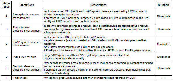
5 Hours* after the ignition switch is turned off, the leak detection pump creates negative pressure (vacuum) in the evap system. The ecm monitors for leaks and actuator malfunctions based on the evap pressure.
Hint:
*: If the engine coolant temperature is not below 35°c (95°f) 5 hours after the ignition switch is turned off, the monitor check starts 2 hours later. If it is still not below 35°c (95°f) 7 hours after the ignition switch is turned to off, the monitor check starts 2.5 Hours later.
![]()
*: If only a small amount of fuel is in the fuel tank, it takes longer for the evap pressure to stabilize.
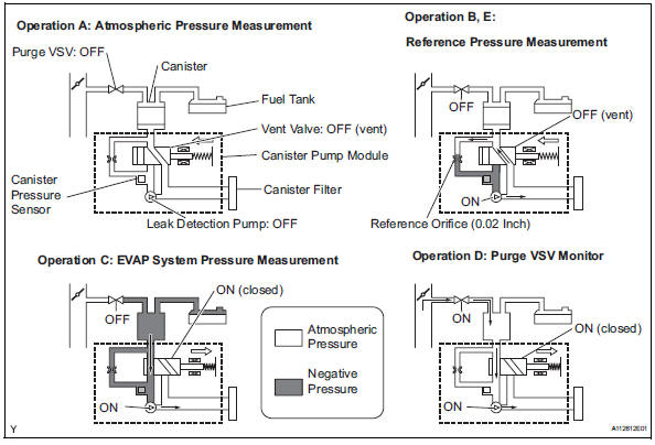
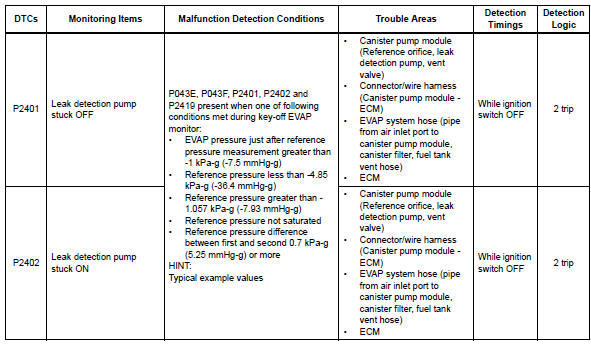
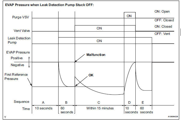
- P2401: leak detection pump stuck off in operation b, the leak detection pump creates negative pressure (a vacuum) through the reference orifice. The evap system pressure is then measured by the ecm, using the canister pressure sensor, to determine the reference pressure. If the pressure is higher than -1.057 Kpa-g (-7.93 Mmhg-g), or lower than -4.85 Kpa-g (-36.4 Mmhg-g), the ecm interprets this as the leak detection pump being stuck off (not operating). The ecm illuminates the mil and sets the dtc (2 trip detection logic).
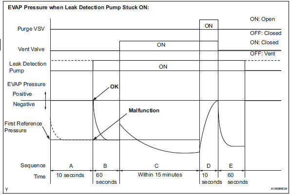
- P2402: leak detection pump stuck on in operation b, the leak detection pump creates negative pressure (a vacuum) through the reference orifice. The evap (evaporative emission) system pressure is then measured by the ecm, using the canister pressure sensor, to determine the reference pressure. If the pressure is higher than -1.057 Kpa-g (-7.93 Mmhg-g), or lower than -4.85 Kpa-g (-36.4 Mmhg-g), the ecm interprets this as the leak detection pump being stuck on (remaining on all the time). The ecm illuminates the mil and sets the dtc (2 trip detection logic).
Hint:
The detection logic of dtcs p2401 and p2402 is the same because in both cases the reference pressure measured in operation b is compared to the atmospheric pressure registered in operation a.
The ecm calculates the difference between these pressures by deducting [the reference pressure] from [the stored atmospheric pressure], and uses this to monitor the evap system pressure change.
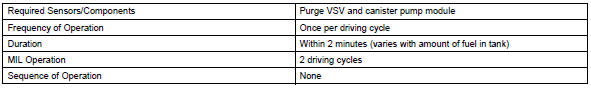
Monitor strategy
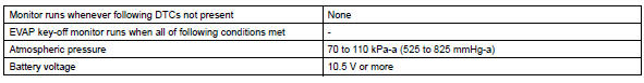
Typical enabling conditions
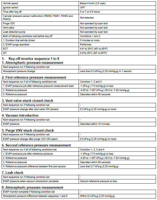
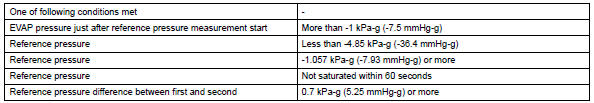
Typical malfunction thresholds
"Saturated" indicates that the evap pressure change is less than 0.286 Kpa-g (2.14 Mmhg-g) in 60 seconds.
Monitor result
Refer to checking monitor status (see page es-17).
 Oxygen (a/f) sensor pumping current circuit
Description
Refer to dtc p2195 (see page es-292).
Monitor description
The air-fuel ratio (a/f) sensor varies its output voltage in proportion to
the air-fuel ratio. If the a/f sensor
imp ...
 Evaporative emission system switching valve control
Dtc summary
Hint:
The vent valve is built into the canister pump module.
Description
The description can be found in the evap (evaporative emission) system (see
page es-335).
Inspection ...
Other materials:
Installation
Install drive plate sub-assembly
Clean the 8 bolts and 8 bolt holes.
Apply adhesive to 2 or 3 threads of the 8 bolts.
Adhesive:
Toyota genuine adhesive 1342, three bond
1342 or equivalent
Using sst, hold the crankshaft.
Sst 09213-54015 (91651-60855), 09330-00021
Instal ...
Disassembly
Remove radiator grille sub-assembly
Remove the 4 bolts and 4 nuts.
Detach the 6 claws and remove the radiator grille.
Remove no. 1 Radiator grille lower
Detach the 18 claws and remove the radiator grille.
Remove no. 2 Radiator grille lower
Detac ...
Fuel injector
Components
Removal
Discharge fuel system pressure
Caution:
Discharge fuel system pressure
procedures must be performed before
disconnecting any part of the fuel system.
After performing the discharge fuel system
pressure procedures, pressure will remain in
the fuel line ...
