Toyota RAV4 (XA40) 2013-2018 Service Manual: Evaporative emission system switching valve control
Dtc summary
Hint:
The vent valve is built into the canister pump module.
Description
The description can be found in the evap (evaporative emission) system (see page es-335).
Inspection procedure
Refer to the evap system (see page es-340).
Monitor description
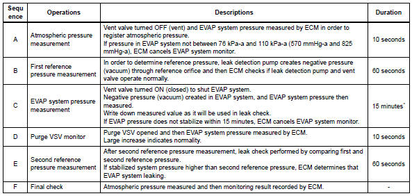
5 Hours* after the ignition switch is turned off, the leak detection pump creates negative pressure (vacuum) in the evap system. The ecm monitors for leaks and actuator malfunctions based on the evap pressure.
Hint:
*: If the engine coolant temperature is not below 35°c (95°f) 5 hours after the ignition switch is turned off, the monitor check starts 2 hours later. If it is still not below 35°c (95°f) 7 hours after the ignition switch is turned off, the monitor check starts 2.5 Hours later.

*: If only a small amount of fuel is in the fuel tank, it takes longer for the evap pressure to stabilize.
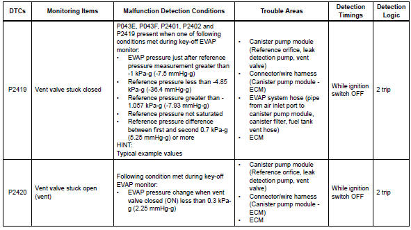
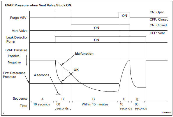
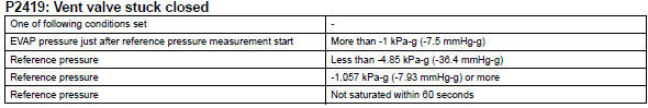
- P2419: vent valve stuck closed
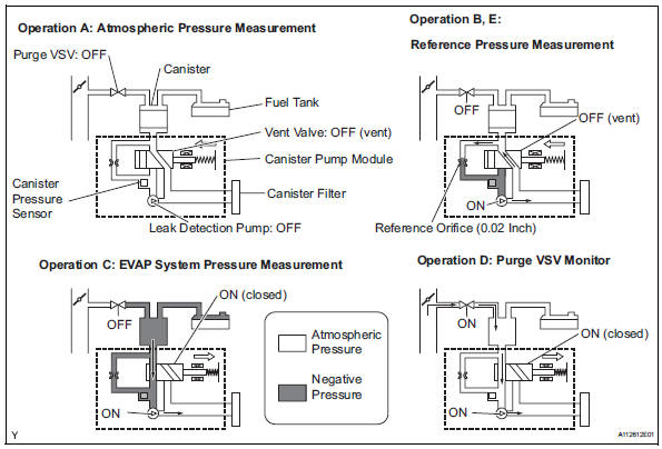
In operation b, the leak detection pump creates negative pressure (a vacuum) through the reference orifice. The evap system pressure is then measured by the ecm, using the canister pressure sensor, to determine the reference pressure. If the pressure exceeds -1.057 Kpa-g (-7.93 Mmhg-g) 4 seconds after the leak detection pump is turned on, the ecm interprets this as the vent valve being stuck closed.
The ecm illuminates the mil and sets the dtc (2 trip detection logic).
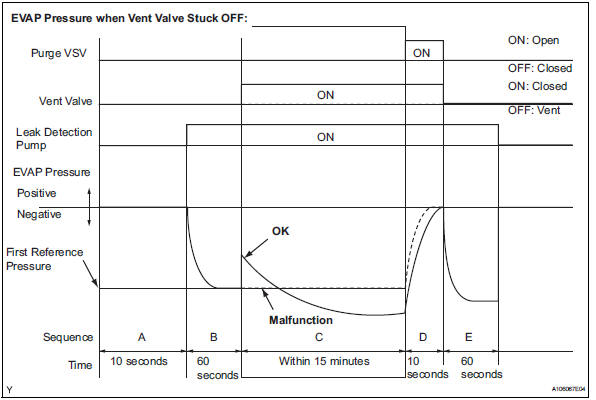
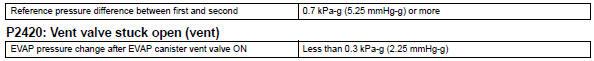
- P2420: vent valve stuck open (vent)
In operation c, the vent valve turns on (closes) and the evap system pressure is then measured by the ecm, using the canister pressure sensor, to conduct an evap leak check. If the pressure does not increase when the vent valve is open, the ecm interprets this as the vent valve being stuck open. The ecm illuminates the mil and sets the dtc.
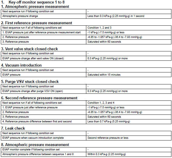
Monitor strategy
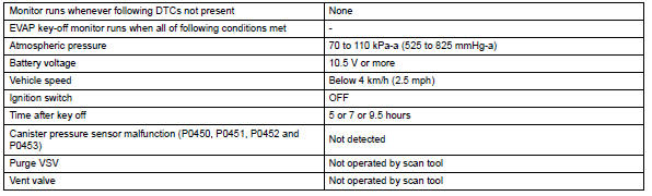
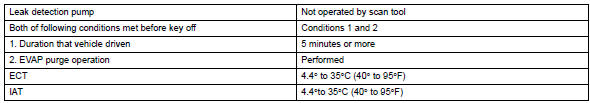
Typical enabling conditions
Typical malfunction thresholds
"Saturated" indicates that the evap pressure change is less than 0.286 Kpa-g (2.14 Mmhg-g) in 60 seconds.
Monitor result
Refer to checking monitor status (see page es-17).
 Evaporative emission leak detection pump
Dtc summary
Hint:
The leak detection pump is built into the canister pump module.
Description
The description can be found in the evap (evaporative emission) system (see
page es-335).
I ...
 Ecm / pcm internal engine off timer performance
Dtc summary
Description
To ensure the accuracy of the evap (evaporative emission) monitor values, the
soak timer, which is built
into the ecm, measures 5 hours (+-15 minutes) from when th ...
Other materials:
Engine immobilizer system
The vehicle's keys have
built-in transponder chips
that prevent the engine from
starting if a key has not
been previously registered
in the vehicle's on-board
computer.
Never leave the keys inside
the vehicle when you leave
the vehicle.
This system is designed to
help prevent vehicle theft but
does ...
Disassembly
Remove no. 3 Heater to register duct
Detach the 6 claws and remove the heater to
register duct.
Remove air duct
Detach the 2 claws and remove the air duct.
Remove air outlet control servo motor
Remove the 3 screws.
Detach the evaporator case from the ...
Diagnosis system
Description
When troubleshooting obd ii (on-board diagnostics)
vehicles, the intelligent tester (complying with sae
j1987) must be connected to the dlc3 (data link
connector 3) of the vehicle. Various data in the vehicle's
ecm (engine control module) can be then read.
Obd ii regulations ...
