Toyota RAV4 (XA40) 2013-2018 Service Manual: Vc output circuit
Description
The ecm constantly generates 5 v power from the battery voltages supplied to the +b (batt) terminal to operate the microprocessor. The ecm also provides this power to the sensors through the vc output circuit.
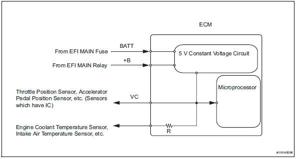
When the vc circuit is short-circuited, the microprocessor in the ecm and sensors that are supplied with power through the vc circuit are inactivated because the power is not supplied from the vc circuit. Under this condition, the system does not start up and the mil does not illuminate even if the system malfunctions.
Hint:
Under normal conditions, the mil is illuminated for several seconds when the ignition switch is first turned on. The mil goes off when the engine is started.
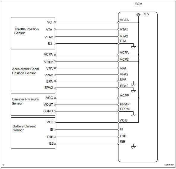
Wiring diagram
Inspection procedure
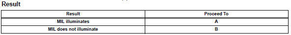
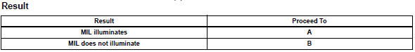
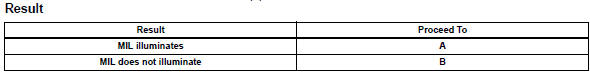
- Check mil
- Check that the malfunction indicator lamp (mil) lights up when turning the ignition switch on.
Ok: mil lights up


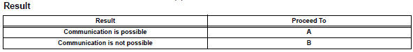
- Check communication between intelligent tester and ecm
- Connect the intelligent tester to the dlc3.
- Turn the ignition switch on and tester on.
- Check the communication between the tester and ecm.


- Check mil (throttle position sensor)
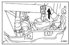
- Disconnect the b3 throttle body connector.
- Turn the ignition switch on.
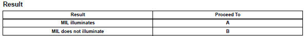
- Check the mil.
- Reconnect the throttle body connector.


- Check mil (accelerator pedal position sensor)
- Disconnect the a4 accelerator pedal position sensor connector.
- Turn the ignition switch on.
- Check the mil.
- Reconnect the accelerator pedal position sensor connector.

- Check mil (canister pump module)
- Disconnect the s3 canister pump module connector.
- Turn the ignition switch on.
- Check the mil.
- Reconnect the canister pump module connector.

- Check mil (battery current sensor)
- Disconnect the b29 battery current sensor connector.
- Turn the ignition switch on.
- Check the mil.
- Reconnect the battery current sensor connector.


- Check harness and connector
- Disconnect the b3 throttle body connector.
- Disconnect the a4 accelerator pedal position sensor connector.
- Disconnect the s3 canister pump module connector.
- Disconnect the b29 battery current sensor connector.
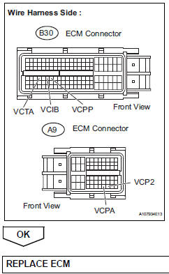
- Disconnect the a9 and b30 ecm connectors.
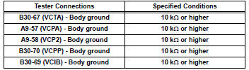
- Measure the resistance.
Standard resistance (check for short)
- Reconnect the throttle body connector.
- Reconnect the accelerator pedal position sensor connector.
- Reconnect the canister pump module connector.
- Reconnect the battery current sensor connector.
- Reconnect the ecm connectors.
 Ecm power source circuit
Description
When the ignition switch is turned on, the battery voltage is applied to the
igsw of the ecm. The output
signal from the mrel terminal of the ecm causes a current to flow to the coil, ...
 Fuel pump control circuit
Description
When the engine is cranked, the starter relay drive signal output from the
star terminal of the ecm is
input into the sta terminal of the ecm, and ne signal generated by the
cranksha ...
Other materials:
Control module communication bus off
Description
Inspection procedure
The skid control ecu inputs the signals from the ecm, steering angle sensor,
and yaw rate and
acceleration sensor via can communication system.
Check harness and connector (momentary interruption)
Using the data list of the intelligent test ...
Freeze frame data
Freeze frame data
Notice:
It is difficult to show the specified values
(judgment values) clearly because freeze frame
data values change significantly due to
differences in measurement conditions,
surroundings, or vehicle conditions. For this
reason, there may be a problem even w ...
Opening/closing the back
door (vehicles with power
back door)
â– Using the wireless remote
control
Press and hold the switch.
The power back door automatically
opens/closes.
Pressing the switch while the power
back door is opening/closing stops
the operation. When the switch is
pressed and held again during the
halted operation, the back door will
perform t ...
