Toyota RAV4 (XA40) 2013-2018 Service Manual: Ecm power source circuit
Description
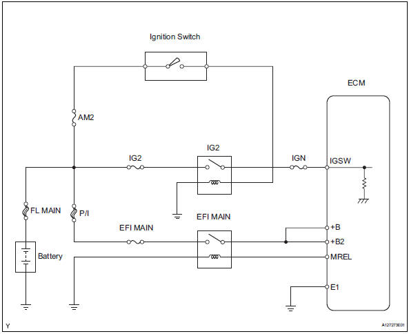
When the ignition switch is turned on, the battery voltage is applied to the igsw of the ecm. The output signal from the mrel terminal of the ecm causes a current to flow to the coil, closing the contacts of the integration relay (efi main relay) and supplying power to either terminal +b or +b2 of the ecm.
Wiring diagram
Inspection procedure
- Inspect fuses (p/i, am2, ig2, efi main, ign)
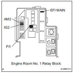
- Remove the p/i fuse, am2 fuse, ig2 fuse and efi main fuse from the engine room no. 1 Relay block.
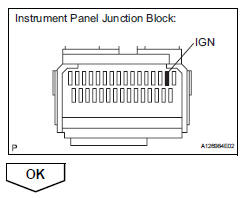
- Remove the ign fuse from the instrument panel junction block.
- Measure the resistance of the fuses.
Standard resistance: below 1

- Reinstall the fuses.
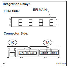
- Inspect relay (ig2, efi main)
- Remove the integration relay and ig2 relay from the engine room no. 1 Relay block.
- Measure the resistance between the terminal of the integration relay.
Standard resistance 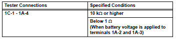
- Measure the resistance between the terminal of the ig2 relay.
Standard resistance 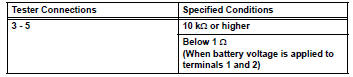
- Reinstall the relay.

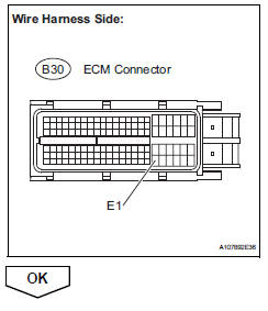
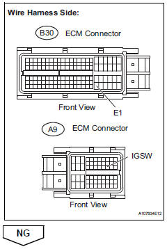
- Check harness and connector (ecm - body ground)
- Disconnect the b30 ecm connector.
- Measure the resistance.
Standard resistance 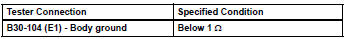
- Reconnect the ecm connector.
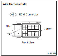
- Inspect ecm (igsw voltage)
- Disconnect the b30 and a9 ecm connectors.
- Turn the ignition switch on.
- Measure the voltage between the terminals of the b30 and a9 ecm connectors.
Standard voltage 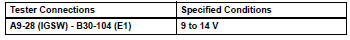
- Reconnect the ecm connector.

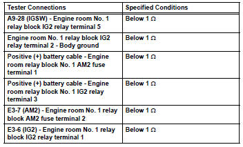
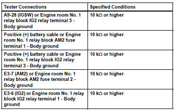
- Check harness and connector (relay block - ecm, ignition switch, battery)
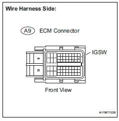
- Disconnect the a9 ecm connector.
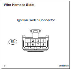
- Disconnect the e3 ignition switch connector.
- Disconnect the battery positive terminal.
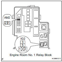
- Remove the am2 fuse and ig2 relay.
- Measure the resistance between the terminals.
Standard resistance (check for open)
Standard resistance (check for short)
- Reinstall the relay and fuse.
- Reconnect the connectors.

- Inspect ignition switch (see page es-261)

- Check harness and connector (integration relay - ecm, battery, body ground)
- Disconnect the a9 ecm connector.
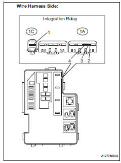
- Remove the integration relay from the engine room no. 1 Relay block.
- Disconnect the integration relay connector.
- Remove the p/i fuse from the engine room no. 1 Relay block.
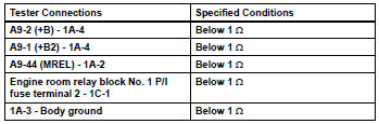
- Check the resistance between the terminals.
Standard resistance (check for open)
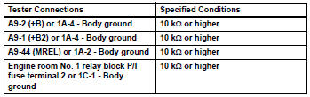
Standard resistance (check for short)
- Reconnect the connectors.
- Reinstall the integration relay and p/i fuse.
 Evap system
Related dtcs
If any evap system dtcs are set, the malfunctioning area can be determined
using the table below.
Notice:
If the reference pressure difference between the first and second ch ...
 Vc output circuit
Description
The ecm constantly generates 5 v power from the battery voltages supplied to
the +b (batt) terminal to
operate the microprocessor. The ecm also provides this power to the sensors
thr ...
Other materials:
Diagnosis system
Description
Engine immobiliser system data and diagnostic
trouble codes (dtcs) can be read through the
vehicle's data link connector 3 (dlc3). In some
cases, a malfunction may be occurring in the engine
immobiliser system even though the security
indicator light is not illuminated ...
Inspection
Inspect water pump assembly
Visually check the drain hole for coolant leakage.
If leakage is found, replace the water pump
assembly.
Turn the pulley, and then check that the water pump
bearing moves smoothly without making a "click"
noise.
If it does not move s ...
Room light assembly
Components
Removal
Disconnect cable from negative battery
terminal
Caution:
Wait at least 90 seconds after disconnecting the
cable from the negative (-) battery terminal to
prevent airbag and seat belt pretensioner activation.
Remove room light lens
Using a screwdriver ...
