Toyota RAV4 (XA40) 2013-2018 Service Manual: Installation
- Install water pump assembly
- Remove any old seal packing material from the contact surface.
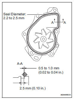
- Apply a continuous line of seal packing as shown in the illustration.
Seal packing: toyota genuine seal parking black, three bond 1207b or equivalent
Standard seal diameter: 2.2 To 2.5 Mm (0.09 To 0.10 In.)
Notice:
- Remove any oil from the contact surface.
- The parts must be set within 3 minutes after applying seal packing. Otherwise, the material must be removed and reapplied.
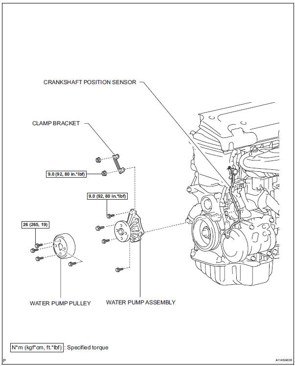
- Install the water pump and clamp bracket with the 4
bolts and 2 nuts.
Torque: 9.0 N*m (92 kgf*cm, 80 in.*Lbf)
- Install the wire of the crankshaft position sensor onto the clamp bracket.
- Install the clamp of the crankshaft position sensor onto the water pump.
- Install water pump pulley
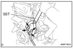
- Using sst, install the water pump pulley with the 4 bolts.
Sst 09960-10010 (09962-01000, 09963-00700) torque: 26 n*m (265 kgf*cm, 19 ft.*Lbf)
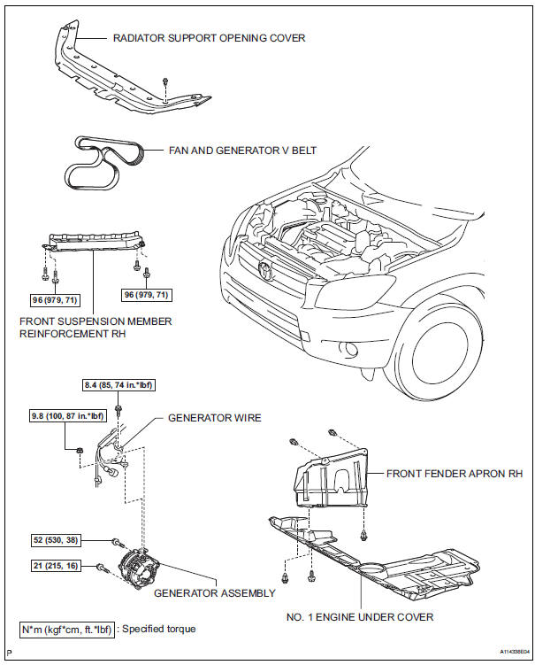
- Install generator assembly (see page ch-15)
- Install fan and generator v belt (see page em-7)
- Install front suspension member reinforcement rh (see page em-7)
- Connect cable to negative battery terminal
- Add engine coolant (see page co-6)
- Check for engine coolant leaks (see page co-1)
- Install radiator support opening cover
- Install front fender apron rh
- Install no. 1 Engine under cover
Components
 Inspection
Inspect water pump assembly
Visually check the drain hole for coolant leakage.
If leakage is found, replace the water pump
assembly.
Turn the pulley, and then check that the water ...
 Thermostat
Components
Removal
Remove no. 1 Engine under cover
Drain engine coolant (see page co-6)
Remove radiator support opening cover
Disconnect no. 2 Radiator hose
Remove water inlet
R ...
Other materials:
Air conditioning amplifier communication stop mode
Description
Wiring diagram
Inspection procedure
Notice:
Turn the ignition switch off before measuring the resistances
of the main wire and the branch
wire.
After the ignition switch is turned off, check that the key
reminder warning system and light
reminder warning sy ...
Disassembly (2006/01- )
Remove front axle inboard joint boot no. 2
Clamp
One touch type:
using a screwdriver, remove the no. 2 Inboard joint
boot clamp, as shown in the illustration.
Claw engagement type:
using needle-nose pliers, remove the no. 2 Inboard
joint boot clamp, as shown in the illustra ...
If your vehicle overheats
The following may indicate
that your vehicle is overheating.
The engine coolant temperature
gauge shows the red zone or a
loss of engine power is
experienced. (For example,
the vehicle speed does not
increase.)
"Engine Coolant Temp High
Stop in a Safe Place See
Owner's Manual" is shown
on ...
