Toyota RAV4 (XA40) 2013-2018 Service Manual: Customize parameters
Hint:
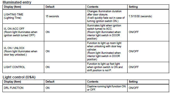
The following items can be customized.
Notice:
- When the customer requests a change in a function, first make sure that the function can be customized.
- Be sure to make a note of the current settings before customizing.
- When troubleshooting a function, first make sure that the function is set to the default setting.
Hint:
Sensitivity adjustments are difficult to confirm. Check by driving the customer's vehicle.
 Operation check
Illuminated entry system operation check
The illuminated entry system controls the following
lights:
Ignition key cylinder light*1 or transponder key
amplifier*2
Foot ligh ...
 Problem symptoms table (2005/11-2006/01)
Hint:
Use the table below to help determine the cause of the
problem symptom. The potential causes of the symptoms are
listed in order of probability in the "suspected area" column of
th ...
Other materials:
Installation (2005/11-2006/01)
Install abs and traction actuator assembly with bracket
Notice:
Do not remove the hole plug before connecting the
brake tube. New actuators are filled with brake fluid.
Install the actuator with bracket with the 3 nuts.
Torque: 19 n*m (194 kgf*cm, 14 ft.*Lbf)
Hint:
The nuts shou ...
Terminals of ecm
Check ecm
Disconnect the a9 and b30 connectors.
Measure the voltage and resistance of the wire
harness side connectors.
If the result is not as specified, there may be a
malfunction on the wire harness side. ...
Wireless remote
control/electronic
key battery
Replace the battery with a new one if it is depleted.
You will need the following items:
Flathead screwdriver
Small flathead screwdriver
Lithium battery cr2016 (vehicles without a smart key system), or
cr2032 (vehicles with a smart key system)
Replacing the battery
Vehicles without a ...
