Toyota RAV4 (XA50) 2019-2026 Owners Manual: Rear seats
Reclining adjustments and folding the seatbacks can be done with lever operation.
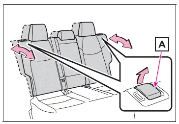
Adjustment procedure
Pull the seatback angle adjustment lever A, and adjust the seatback angle.
WARNING
â– When operating the seatback
Observe the following precautions.
Failure to do so may cause death or serious injury.
- Keep other passengers from being hit with the seatback.
- Do not bring your hands close to the moving parts or between the seats, as well as do not let any part of your body get caught.
- After adjusting the seat, make
sure that the seat is locked in
position.
If the seatback is not securely locked, the red marking will be visible. Make sure that the red marking is not visible.
Folding down the rear seatbacks
â– Before folding down the seatbacks
1. Park the vehicle in a safe place.
Apply the parking brake and shift the shift lever to P.
2. Adjust the position of the front seat and the angle of the seatback.
Depending on the position of the front seat, if the seatback is folded backward, it may interfere with the operation of the rear seat.
3. Lift up and push down the head restraints of the rear outboard seats, and lower the head restraint of the rear center seat. 4. Stow the armrest of the rear seat if it is pulled out.
This step is not necessary when operating the left side seat only.
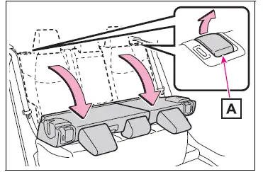
â– Folding down the seatbacks
While pulling the seatback angle adjustment lever A, fold the seatback down.
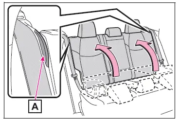
â– Returning the rear seatbacks
To avoid trapping the seat belt between the seat and the inside of the vehicle, pass the seat belt outside the seat belt guide A and then return the seatback securely to the locked position.
WARNING
Observe the following precautions.
Failure to do so may result in death or serious injury.
â– When folding the rear seatbacks down
- Do not fold the seatbacks down while driving.
- Stop the vehicle on level ground, set the parking brake and shift the shift lever to P.
- Do not allow anyone to sit on a folded seatback or in the luggage compartment while driving.
- Do not allow children to enter the luggage compartment.
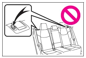
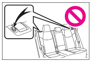
- Do not operate the rear seat if it is occupied.
- Be careful not to get feet or hands caught in the moving parts or joints of the seats during operation.
- Do not allow children to operate the seat.
â– After returning the rear seatback to the upright position
Make sure that the seatback is securely locked in position by lightly pushing it back and forth.
If the seatback is not securely locked, the red marking will be visible. Make sure that the red marking is not visible.
- Check that the seat belts are not twisted or caught in the seatback.
 Front seats
The seats can be adjusted
(longitudinally, vertically,
etc.). Adjust the seat to
ensure the correct driving
posture.
Adjustment procedure
Manual seat
Seat position adjustment
lever
Seatback angle ...
 Driving position memory
This feature automatically
adjusts the driver's seat to
suit your preferences.
Your preferred driving position
(the position of the
driver's seat) can be
recorded and recalled by
pressing a button.
...
Other materials:
Driving information display
â– Drive information
2 items that are selected using
the "Drive Info Items" setting
(average speed and distance)
can be displayed vertically.
Use the displayed information as a
reference only.
"Average Speed": Displays
the average vehicle speed
since engine start*
"Distance": Displays the dist ...
Removal
Disconnect cable from negative battery terminal
Caution:
Wait at least 90 seconds after disconnecting the
cable from the negative (-) battery terminal to
prevent airbag and seat belt pretensioner activation.
Remove mass air flow meter
Disconnect the mass air flow meter connector.
...
Removal
Disconnect cable from negative battery
terminal
Caution:
Wait at least 90 seconds after disconnecting the
cable from the negative (-) battery terminal to
prevent airbag and seat belt pretensioner activation.
Remove air cleaner cap (see page es-411)
Remove air cleaner case
...
