
Toyota RAV4 (XA40) 2013-2018 Service Manual: How to proceed with troubleshooting (2005/11-2006/01)
Hint:
- Use these procedures to troubleshoot the air conditioning system.
- *: Use the intelligent tester.
- Vehicle brought to workshop

- Customer problem analysis and symptom check

- Inspect battery voltage
Standard voltage: 11 to 14 v
If the voltage is below 11 v, recharge or replace the battery before proceeding.

- Check can communication system*
- Use the intelligent tester to check if the can communication system is functioning.
Result 


- Check dtc*
- Check for dtcs and write down any dtcs that are output.
- Clear the dtcs.
- Recheck for dtcs. Based on the dtcs output above, try to cause output of the air conditioning system dtc by simulating the operation indicated by the dtc.
Result 


- Refer to problem symptoms table
Result 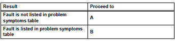


- Overall analysis and troubleshooting*
- Data list / active test (see page ac-127)
- Terminals of ecu (see page ac-122)

- Adjust, repair or replace

- Confirmation test

End
 System description
General
The air conditioning system has the following
features:
The air conditioning amplifier controls the
operation of parts, such as the a/c compressor,
automatically in accord ...
 How to proceed with troubleshooting (2006/01- )
Hint:
Use these procedures to troubleshoot the air conditioning
system
*: Use the intelligent tester.
Vehicle brought to workshop
Customer problem analysis and symptom check
...
Other materials:
Data list / active test
Read data list
Hint:
Using the intelligent tester's data list allows switch,
sensor, actuator and other item values to be read without
removing any parts. Reading the data list early in
troubleshooting is one way to save time.
Connect the intelligent tester to the dlc3.
Turn the igni ...
Rear coil spring
Components
Removal
Hint:
Use the same procedures for the rh side and lh side.
The procedures listed below are for the lh side.
Remove rear wheel
Remove skid control sensor wire (for 2wd)
(see page bc-198)
Remove rear speed sensor lh (for 4wd) (see
page bc-205)
Disconnect ...
Turn signal lever
Operating instructions
Right turn
Lane change to the right (move
the lever partway and release
it)
the right hand signals will flash 3
times.
Lane change to the left (move
the lever partway and release
it)
the left hand signals will flash 3
times.
Left turn
Turn signals ...
