Toyota RAV4 (XA40) 2013-2018 Service Manual: Rear bumper
Components
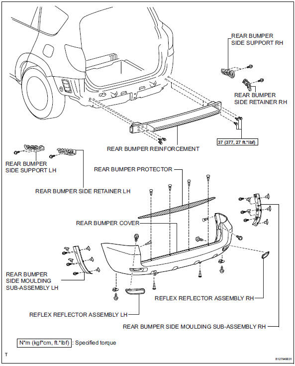
Removal
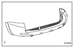
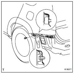
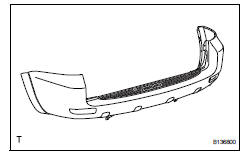
- Remove rear bumper cover
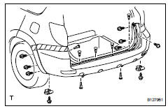
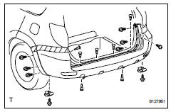
- Remove the 9 screws and 7 clips.
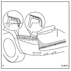
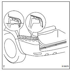
- Put protective tape under the quarter panel.
- Detach the 12 claws and remove the bumper cover.
- Remove rear bumper protector
Hint:
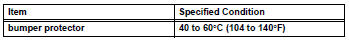
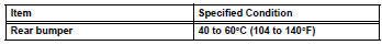
When removing the bumper protector, heat the bumper protector.
Standard heating temperature
- Using a moulding remover, remove the bumper protector.
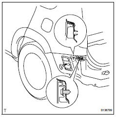
- Remove reflex reflector assembly lh
- Remove the screw and reflex reflector.
- Remove reflex reflector assembly rh
Hint:
Use the same procedures described for the lh side.
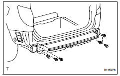
- Remove rear bumper reinforcement
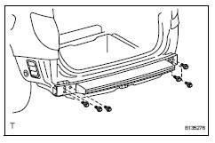
- Remove the 6 bolts and reinforcement.
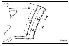
- Remove rear bumper side support lh
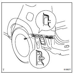
- Remove the 2 screws.
- Using a screwdriver, detach the claw and remove the bumper side support.
Hint:
Tape the screwdriver tip before use.
- Remove rear bumper side support rh
Hint:
Use the same procedures described for the lh side.
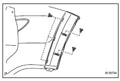
- Remove rear bumper side retainer lh
- Remove the screw.
- Using a screwdriver, detach the claw and remove the side retainer.
Hint:
Tape the screwdriver tip before use.
- Remove rear bumper side retainer rh
Hint:
Use the same procedures described for the lh side.
- Remove rear bumper side moulding subassembly lh (for wide body)
- Detach the 5 outside moulding retainers and remove the moulding.
Notice:
- If reusing the extension, take care not to damage the moulding.
- Be careful not to damage the vehicle body.
- Remove rear bumper side moulding subassembly rh (for wide body)
hint:
Use the same procedures described for the lh side.
Installation
- Install rear bumper side moulding subassembly lh (for wide body)
- Attach the 5 outside moulding retainers to install the moulding.
- Install rear bumper side moulding subassembly rh (for wide body)
Hint:
Use the same procedures described for the lh side.
- Install rear bumper side retainer lh
- Attach the claw to install the side retainer.
- Install the screw.
- Install rear bumper side retainer rh
Hint:
Use the same procedures described for the lh side.
- Install rear bumper side support lh
- Attach the claw to install the bumper side support.
- Install the 2 screws.
- Install rear bumper side support rh
Hint:
Use the same procedures described for the lh side.
- Install rear bumper reinforcement
- Install the bumper reinforcement with the 6 bolts.
Torque: 37 n*m (377 kgf*cm, 27 ft.*Lbf)
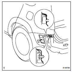
- Install reflex reflector assembly lh
- Install the reflex reflector with the screw.
- Install reflex reflector assembly rh
Hint:
Use the same procedures described for the lh side.
- Install rear bumper protector
Hint:
When removing the double-side tape, heat the rear bumper.
Standard heating temperature
- Clean the bumper surface.
- Using a heat light, heat the bumper surface.
- Remove the double-sided tape from the bumper.
- Wipe off any tape adhesive residue with cleaner.
- Install the new bumper protector.
Install rear bumper cover
- Put protective tape under the quarter panel.
- Attach the 12 claws to install the bumper cover.
- Install the 9 screws and 7 clips.
 Installation
Install front bumper side retainer lh
Install the clip and bumper side retainer.
Install the bolt.
Torque: 6.0 N*m (61 kgf*cm, 53 in.*Lbf)
Install front bumper side retainer rh
...
 Radiator grille
Components
Removal
Remove radiator grille (see page et-6)
Remove no. 1 Radiator grille lower (see
page et-7)
Remove no. 2 Radiator grille lower (see
page et-7)
...
Other materials:
Vin not programmed or mismatch - ecm / pcm
Description
Dtc p0630 is set when the vehicle identification number (vin) is not stored
in the engine control module
(ecm) or the input vin is incorrect. Input the vin with the intelligent tester.
Monitor strategy
Typical enabling conditions
Typical malfunction thresholds
Com ...
Transmitter id not registered in main mode
Description
Inspection procedure
Notice:
It is necessary to register an id code after replacing the tire pressure
warning valve and
transmitter and/or the tire pressure monitor ecu (see page tw-9).
Hint:
Set the tire pressure to the specified value.
Standard pressure:
220 kpa (2.2 ...
Cleaning and protecting
the vehicle exterior
Perform the following to protect the vehicle and maintain it in
prime condition:
Working from top to bottom, liberally apply water to the vehicle
body, wheel wells and underside of the vehicle to remove any dirt
and dust.
Wash the vehicle body using a sponge or soft cloth, such as a
cha ...
