Toyota RAV4 (XA40) 2013-2018 Service Manual: Terminals of ecu (2006/01- )
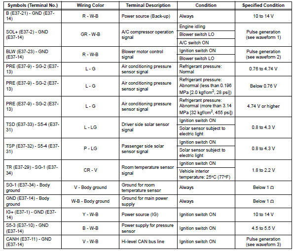
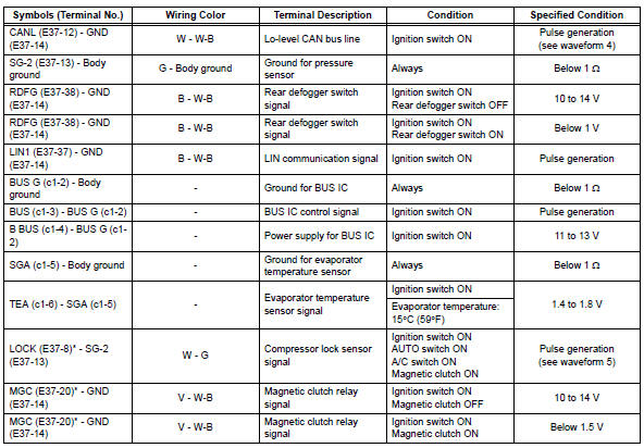
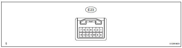
- Check air conditioning amplifier
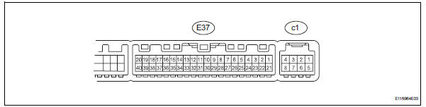
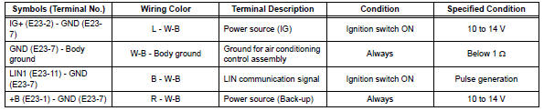
- Measure the voltage and resistance of the connectors.
Hint:
Check from the rear of the connector while it is connected to the air conditioning amplifier.
Hint:
*: For 2gr-fe
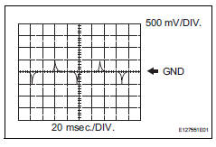
- Using an oscilloscope, check waveform 1.
A/c compressor* operation signal
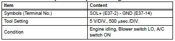
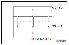
Hint:
*: Compressor and pulley for 2az-fe, compressor and magnetic clutch for 2gr-fe.
- Using an oscilloscope, check waveform 2.
Blower motor control signal 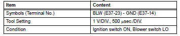
Hint:
When the blower level is increased, the duty ratio changes accordingly.
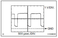
- Using an oscilloscope, check waveform 3.
Can communication signal 
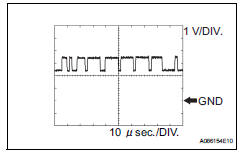
Hint:
The waveform varies depending on the can communication signal.
- Using an oscilloscope, check waveform 4.
Can communication signal 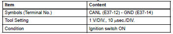
Hint:
The waveform varies depending on the can communication signal.
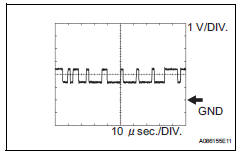
- Using an oscilloscope, check waveform 5.
Compressor lock sensor signal* 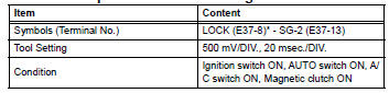
Hint:
*: For 2gr-fe
- Check air conditioning control
- Measure the voltage and resistance of the connectors.

 Terminals of ecu (2005/11-2006/01)
Check air conditioning amplifier
Measure the voltage and resistance of the
connectors.
Hint:
Check from the rear of the connector while it is
connected to the air conditioning ampl ...
 Diagnosis system
Description
Air conditioning system data and the diagnostic
trouble codes (dtcs) can be read through the
data link connector 3 (dlc3) of the vehicle. When
the system seems to be malfunc ...
Other materials:
Installation
Caution:
Be sure to read the precautionary notices concerning the
srs airbag system before servicing it (see page rs-1).
Install steering pad assembly
Support the steering pad with one hand as shown in
the illustration.
Connect the 2 airbag connectors.
Notice:
When handling t ...
Data list / active test (2005/11-2006/01)
Read data list
Read data list
Hint:
Using the intelligent tester's data list allows switch,
sensor, actuator and other item values to be read without
removing any parts. Reading the data list early in
troubleshooting is one way to save time.
Connect the intelligent tester (wi ...
Using the radio
Power
Volume
Adjusting the frequency
Scanning for receivable stations
Am/fm mode button
Station selectors
Seeking the frequency
Displaying text message
Setting station presets
Search for the desired stations by turning the ¢┬¦tune¢escroll¢¸
knob or ...
