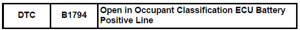
Toyota RAV4 (XA40) 2013-2018 Service Manual: Open in occupant classification ecu battery positive line
Description
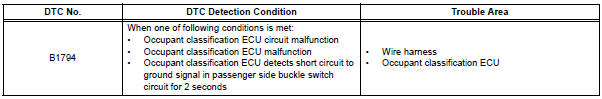
Dtc b1794 is set when a malfunction is detected in the occupant classification ecu battery positive line.
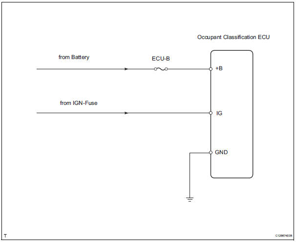
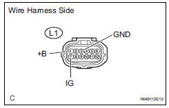
Wiring diagram
Inspection procedure
- Check for dtc
- Turn the ignition switch on.
- Clear the dtcs (see page rs-249).
Hint:
First clear dtcs stored in the occupant classification ecu and then in the center airbag sensor.
- Turn the ignition switch off, and wait for at least 10 seconds.
- Turn the ignition switch on.
- Check the dtcs (see page rs-249).
Ok: dtc b1794 is not output.
Hint:
Dtcs other than b1794 may be output at this time, but they are not related to this check.

- Check connection of connector
- Turn the ignition switch off.
- Disconnect the cable from the negative (-) battery terminal, and wait for at least 90 seconds.
- Check that the connectors are properly connected to the occupant classification ecu.
Ok: the connectors are properly connected.


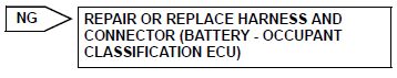
- Check wire harness (source voltage)
- Turn the ignition switch off.
- Disconnect the cable from the negative (-) battery terminal, and wait for at least 90 seconds.
- Disconnect the l1 connector from the occupant classification ecu.
- Connect the cable to the negative (-) battery terminal, and wait for at least 2 seconds.
- Measure the voltage of the wire harness side connector.
Standard voltage 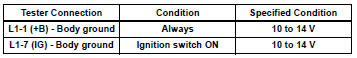
- Measure the resistance of the wire harness side connector.
Standard resistance 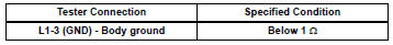

- Check for dtc
- Turn the ignition switch off.
- Disconnect the cable from the negative (-) battery terminal, and wait for at least 90 seconds.
- Connect the connectors to the occupant classification ecu.
- Connect the cable to the negative (-) battery terminal, and wait for at least 2 seconds.
- Turn the ignition switch on.
- Clear the dtcs (see page rs-249).
Hint:
First clear dtcs stored in the occupant classification ecu and then in the center airbag sensor.
- Turn the ignition switch off, and wait for at least 10 seconds.
- Turn the ignition switch on.
- Using the intelligent tester, check for dtcs of the occupant classification ecu (see page rs-249).
Ok: dtc b1794 is not output.
Hint:
Dtcs other than b1794 may be output at this time, but they are not related to this check.


- Replace occupant classification ecu
- Turn the ignition switch off.
- Disconnect the cable from the negative (-) battery terminal, and wait for at least 90 seconds.
- Replace the occupant classification ecu (see page rs- 392).
Hint:
Perform the inspection using parts from a normal vehicle when possible.

- Perform zero point calibration
- Connect the cable to the negative (-) battery terminal, and wait for at least 2 seconds.
- Connect the intelligent tester (with can vim) to the dlc3.
- Turn the ignition switch on.
- Using the intelligent tester, perform the zero point calibration (see page rs-241).
Ok: completed is displayed.

- Perform sensitivity check
- Using the intelligent tester, perform the sensitivity check (see page rs-241).
Standard value: 27 to 33 kg (59.52 To 72.75 Lb)

End
 Occupant classification sensor power supply circuit malfunction
Description
The occupant classification sensor power supply circuit consists of the
occupant classification ecu and
the occupant classification sensors.
Dtc b1793 is recorded when a malfunc ...
 Occupant classification ecu malfunction
Description
Dtc b1795 is recorded when a malfunction is detected in the occupant
classification ecu.
Troubleshoot dtc b1771 first when dtc b1771 and b1795 are output simultaneously.
Wir ...
Other materials:
Driver side - side airbag sensor assembly initialization incomplete
Description
The side airbag sensor lh consists of part including the diagnostic circuit
and the lateral deceleration
sensor.
When the center airbag sensor receives signals from the lateral deceleration
sensor, it determines
whether or not the srs should be activated.
Dtc b1623/81, b ...
Registration
Hint:
The key has 2 codes: the key code (immobiliser code) and
the wireless code (recognition code). Both of these codes
need to be registered. For wireless code registration
procedures, refer to the following procedures (see page dl-
46). For key code registration procedures, refer to the
pro ...
The rear cross traffic alert function detection areas
The areas that vehicles can be detected in are outlined below.
To give the driver a more consistent time to react, the buzzer can alert
for faster vehicles from farther away.
Example:
The rear cross traffic alert function is operational when
The bsm main switch is set to on.
The shift ...
