Toyota RAV4 (XA40) 2013-2018 Service Manual: Steering angle sensor circuit malfunction
![]()
Description
The steering sensor signal is sent to the skid control ecu via the can communication system. When there is a malfunction in the can communication system, it is detected by the steering sensor zero point malfunction diagnostic function.
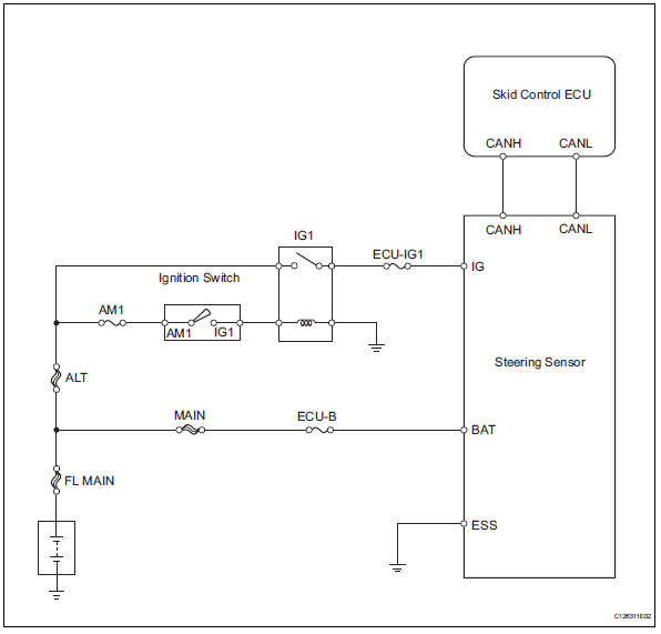
Wiring diagram
Inspection procedure
Hint:
- When u0073/94, u0123/62, u0124/95 or u0126/63 is output together with c1231/31, inspect and repair the trouble areas indicated by u0073/94, u0123/62, u0124/95 or u0126/63 first.
- When there are problems with the speed sensor or the yaw rate sensor, dtcs for the steering sensor may be output even when the steering sensor is normal. When dtcs for the speed sensor or yaw rate sensor are output together with other dtcs for the steering sensor, inspect and repair the speed sensor and yaw rate sensor first, and then inspect and repair the steering sensor.
- Check harness and connector (momentary interruption)
- Using the data list of the intelligent tester, check for any momentary interruptions in the wire harness and connectors between the skid control ecu and the steering sensor (see page bc-23).
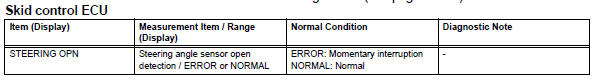
Ok: there are no momentary interruptions.
Hint:
Perform the above inspection before removing the sensor and connector.

- Check dtc
- Clear the dtc (see page bc-47).
- Turn the ignition switch off
- Turn the ignition switch on again and check that no can communication system dtc is output.
- Drive the vehicle and turn the steering wheel to the right and left at a speed of 35 km/h (24 mph) and check that no speed and yaw rate sensor dtcs are output.
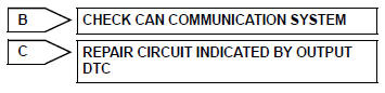
Result 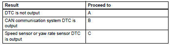

- Check wire harness (steering sensor - battery and body ground)
- Remove the steering wheel assembly and the column cover.
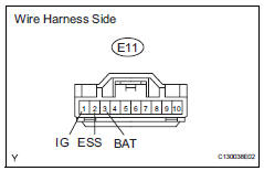
- Disconnect the e11 sensor connector.
- Measure the voltage of the wire harness side connector.
Standard voltage 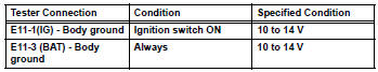
- Measure the resistance of the wire harness side connector.
Standard resistance 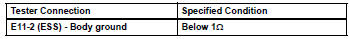

Replace steering sensor
- Repair or replace harness and connector (steering sensor to skid control ecu)

- Reconfirm dtc
- Clear the dtc (see page bc-47).
- Start the engine.
- Drive the vehicle and turn the steering wheel to the right and left at a speed of 45 km/h (28 mph) or more for several seconds.
- Check if the same dtc is recorded (see page bc-47).
Result 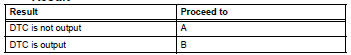

End
 Abs control system malfunction
Description
This dtc is output when the vsc system detects a malfunction in the abs
system.
Inspection procedure
Check dtc for abs system
Clear the dtc (see page bc-47).
Turn t ...
 Stuck in deceleration sensor
Description
The skid control ecu receives signals from the yaw rate and deceleration
sensor via the can
communication system.
The yaw rate sensor has a built-in deceleration sensor and dete ...
Other materials:
Types of child restraints
Child restraint systems are classified into the following 3 types
according to the age and size of the child:
Rear facing „o infant seat/convertible
seat
Forward facing „o convertible
seat
Booster seat
Selecting an appropriate child restraint system
Use a child restraint ...
Moon roof
Use the overhead switches
to open and close the moon
roof and tilt it up and down.
Operating the moon roof
â– Opening and closing
Opens the moon roof*
The moon roof stops slightly before
the fully open position to reduce
wind noise.
Press the switch again to fully open
the moon roof.
Close ...
Automatic transaxle assembly
Components
Removal
Remove engine assembly with transaxle
Remove the engine with transaxle (see page em-
98).
Drain automatic transaxle fluid
Remove the drain plug and gasket, and drain atf.
Install a new gasket and the drain plug.
Torque: 47 n*m (479 kgf*cm, 35 ft. ...
