Toyota RAV4 (XA40) 2013-2018 Service Manual: Can bus line
Description
When any dtc for the can communication system is output, first measure the resistance between the terminals of the dlc3 to specify the trouble area, and check that there is not a short in the can main wire, between the main wire, to +b, or to gnd.
Wiring diagram
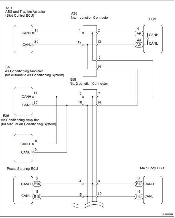
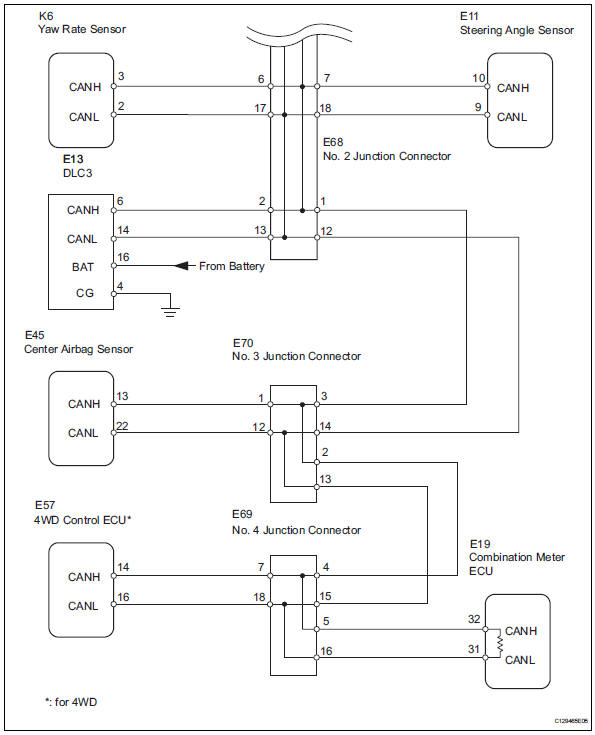
Inspection procedure
Notice:
- Turn the ignition switch off before measuring the resistances of the main wire and the branch wire.
- After the ignition switch is turned off, check that the key reminder warning system and light reminder warning system are not in operation.
- Before measuring the resistance, leave the vehicle for at least 1 minute and do not operate the ignition switch, any switches or doors. If doors need to be opened in order to check connectors, open the doors and leave them open.
Hint:
Operating the ignition switch, any switches or any doors triggers related ecu and sensor communication with the can, which causes resistance variation.
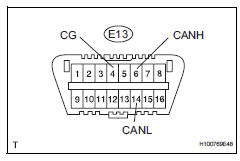
- Check can bus wire (main wire for open, can bus lines for short circuit)
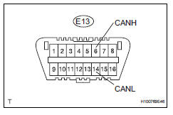
- Measure the resistance of the dlc3.
Standard resistance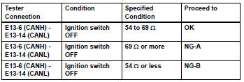

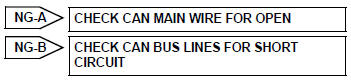
- Check can bus line for short to +b
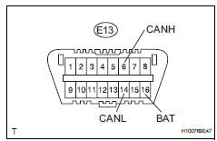
- Measure the resistance of the dlc3.
Standard resistance 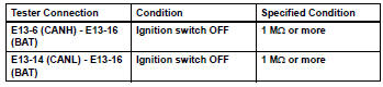

- Check can bus line for short to gnd
- Measure the resistance of the dlc3.
Standard resistance 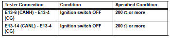

Check how to proceed with troubleshooting
 4Wd control ecu communication stop mode
Description
Hint:
For vehicle with 4wd only.
Wiring diagram
Inspection procedure
Notice:
Turn the ignition switch off before measuring the resistances of the
main wire and the bra ...
 Open in can main wire
Description
There may be an open circuit in the can main wire and / or the dlc3 branch
wire when the resistance
between terminals 6 (canh) and 14 (canl) of the dlc3 is 69 ù or more.
Wi ...
Other materials:
Front door lock
Inspection
Inspect front door with motor lock assembly lh
Apply the battery voltage to the motor terminals and
check the operation of the door lock motor.
Ok
If the result is not as specified, replace the door lock
assembly.
Measure the resistance of the door lock position
...
Reassembly
Install sliding roof drive cable
Using a screwdriver, slide the sliding roof drive
cable sub-assemblies in the direction indicated by
the arrow in the illustration to install them.
Hint:
Tape the screwdriver tip before use.
Engage the 2 claws and install the sliding roof ...
Garage door opener
The garage door opener can
be programmed using the
HomeLink to operate
garage doors, gates, entry
doors, door locks, home
lighting systems, security
systems, and other devices.
â– HomeLink programming procedure
The programming procedures can
also be found at the following URL.
System components
The ...
