Toyota RAV4 (XA40) 2013-2018 Service Manual: Open in can main wire
Description
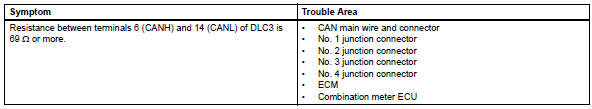
There may be an open circuit in the can main wire and / or the dlc3 branch wire when the resistance between terminals 6 (canh) and 14 (canl) of the dlc3 is 69 ù or more.
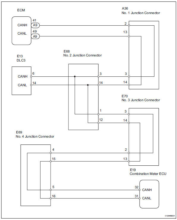
Wiring diagram
Inspection procedure
Notice:
- Turn the ignition switch off before measuring the resistances of the main wire and the branch wire.
- After the ignition switch is turned off, check that the key reminder warning system and light reminder warning system are not in operation.
- Before measuring the resistance, leave the vehicle for at least 1 minute and do not operate the ignition switch, any switches or doors. If doors need to be opened in order to check connectors, open the doors and leave them open.
Hint:
Operating the ignition switch, any switches or any doors triggers related ecu and sensor communication with the can, which causes resistance variation.
- Check dlc3
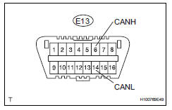
- Measure the resistance of the dlc3.
Standard resistance 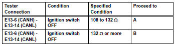
Notice:
When the measured value is 132 ù or more and a can communication system diagnostic trouble code is output, there may be a fault besides disconnection of the dlc3 branch wire. For that reason, troubleshooting should be performed again from "how to proceed with troubleshooting" (see page ca-8) after repairing the trouble area.

- Check can main wire for disconnection (no. 2 Junction connector - ecm)
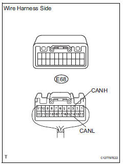
- Disconnect the e68 no. 2 Junction connector.
- Measure the resistance of the wire harness side connector.
Standard resistance 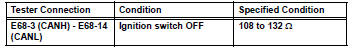

- Check can main wire for disconnection (no. 2 Junction connector - combination meter ecu)
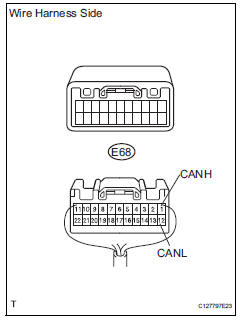
- Measure the resistance of the wire harness side connector.
Standard resistance 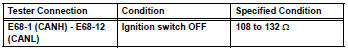

Replace no. 2 Junction connector
- Connect connector
- Reconnect the e68 no. 2 Junction connector.

- Check can main wire for disconnection (no. 1 Junction connector - ecm)
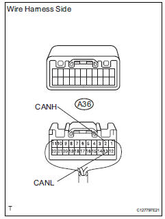
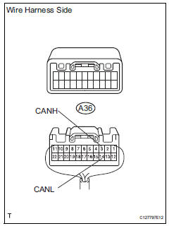
- Disconnect the a36 no. 1 Junction connector.
- Measure the resistance of the wire harness side connector.
Standard resistance 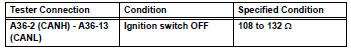

- Check can main wire for disconnection (no. 1 Junction connector - no. 2 Junction connector)
- Measure the resistance of the wire harness side connector.
Standard resistance 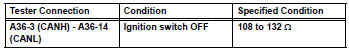

Replace no. 1 Junction connector
- Connect connector
- Reconnect the a36 no. 1 Junction connector.

- Check can main wire for disconnection (ecm - no. 1 Junction connector)
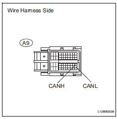
- Disconnect the a9 ecm connector.
- Measure the resistance of the wire harness side connector.
Standard resistance 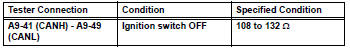

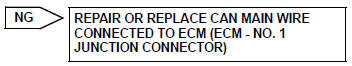
Replace ecm
- Connect connector
- Reconnect the e68 no. 2 Junction connector.

- Check can main wire for disconnection (no. 4 Junction connector - no. 2 Junction connector)
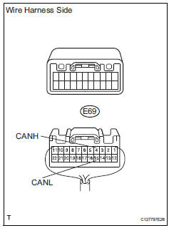
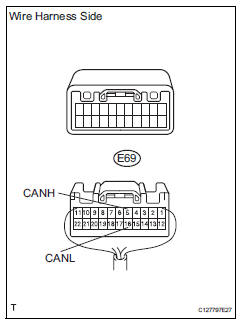
- Disconnect the e69 no. 4 Junction connector.
- Measure the resistance of the wire harness side connector.
Standard resistance 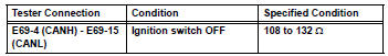


- Check can main wire for disconnection (no. 4 Junction connector - combination meter)
- Measure the resistance of the wire harness side connector.
Standard resistance 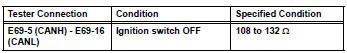


Replace no. 4 Junction connector
- Connect connector
- Reconnect the e69 no. 4 Junction connector.

- Check can main bus line for disconnection (combination meter ecu - no. 4 Junction connector)
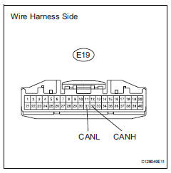
- Disconnect the e19 combination meter ecu connector.
- Measure the resistance of the wire harness side connector.
Standard resistance 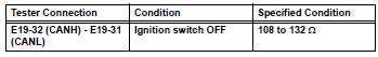

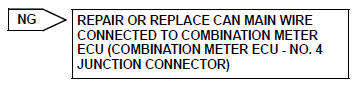
Replace combination meter assembly (combination meter ecu)
- Connect connector
- Reconnect the e69 no. 4 Junction connector.

- Check can main wire for disconnection (no. 2 Junction connector - no. 3 Junction connector)
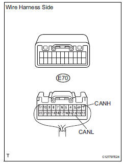
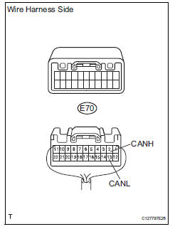
- Disconnect the e70 no. 3 Junction connector.
- Measure the resistance of the wire harness side connector.
Standard resistance 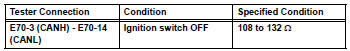

- Check can main wire for disconnection (no. 3 Junction connector - no. 4 Junction connector)
- Measure the resistance of the wire harness side connector.
Standard resistance 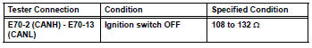

Replace no. 3 Junction connector
 Can bus line
Description
When any dtc for the can communication system is output, first measure the
resistance between the
terminals of the dlc3 to specify the trouble area, and check that there is not a
sho ...
 Short in can bus lines
Description
There may be a short circuit between the can bus lines when the resistance
between terminals 6 (canh)
and 14 (canl) of the dlc3 is below 54
.
Wiring diagram
Inspection ...
Other materials:
Reassembly
Install piston
Using a small screwdriver, install a new snap ring
onto one end of the piston pin hole.
Hint:
Make sure that the end gap of the snap ring is not
aligned with the pin hole cutout portion of the piston.
Gradually heat the piston up to 80 to 90°c (176 to
194°f ...
Throttle actuator control throttle body range / performance
Description
The electronic throttle control system (etcs) is composed of the throttle
actuator, throttle position (tp)
sensor, accelerator pedal position (app) sensor, and ecm. The ecm operates the
throttle actuator to
regulate the throttle valve in response to driver inputs. The tp senso ...
Camshaft position sensor "a" circuit (bank 1 or single sensor)
Description
The camshaft position (cmp) sensor consists of a magnet and an iron core
which is wrapped with copper
wire, and is installed onto the cylinder head. When the camshaft rotates, each
of 3 teeth on the camshaft
passes through the cmp sensor. This activates the internal magnet in ...
