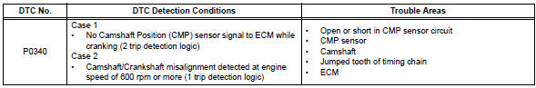
Toyota RAV4 (XA40) 2013-2018 Service Manual: Camshaft position sensor "a" circuit (bank 1 or single sensor)

Description
The camshaft position (cmp) sensor consists of a magnet and an iron core which is wrapped with copper wire, and is installed onto the cylinder head. When the camshaft rotates, each of 3 teeth on the camshaft passes through the cmp sensor. This activates the internal magnet in the sensor, generating a voltage in the copper wire. The camshaft rotation is synchronized with the crankshaft rotation. When the crankshaft turns twice, the voltage is generated 3 times in the cmp sensor. The generated voltage in the sensor acts as a signal, allowing the ecm to locate the camshaft position. This signal is then used to control ignition timing, fuel injection timing, and the vvt system.
Hint:
Dtc p0340 indicates a malfunction relating to the cmp sensor (+) circuit (the wire harness between the ecm and cmp sensor, and the cmp sensor itself).
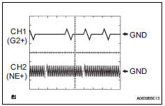
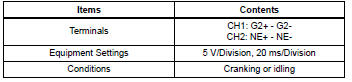
Reference: inspection using an oscilloscope
Hint:
- The correct waveform is as shown in the illustration.
- G2+ stands for the cmp sensor signal, and ne+ stands for the crankshaft position (ckp) sensor signal.
- Grounding failure of the shielded wire may cause noise in waveforms.
Monitor description
If no signal is transmitted by the cmp sensor despite the engine revolving, or the rotation of the camshaft and the crankshaft is not synchronized, the ecm interprets this as a malfunction of the sensor.
If the malfunction is not repaired successfully, a dtc is set 10 seconds after the engine is next started.
Monitor strategy
![]()
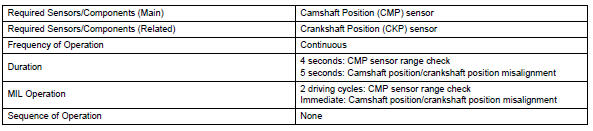
Typical enabling conditions
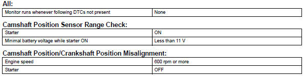
Typical malfunction thresholds
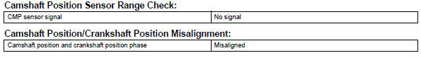
Component operating range
![]()
Wiring diagram
Refer to dtc p0335 (see page es-174).
Inspection procedure
Hint:
Read freeze frame data using the intelligent tester. Freeze frame data records the engine condition when malfunctions are detected. When troubleshooting, freeze frame data can help determine if the vehicle was moving or stationary, if the engine was warmed up or not, if the air-fuel ratio was lean or rich, and other data from the time the malfunction occurred.
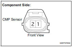
- Inspect camshaft position sensor (resistance)
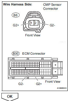
- Disconnect the b6 camshaft position (cmp) sensor connector.
- Measure the resistance between terminals 1 and 2.
Standard resistance 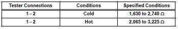
Hint:
Terms cold and hot refer to the temperature of the sensor. Cold means approximately -10° to 50°c (14 °to 122°f). Hot means approximately 50° to 100°c (122°to 212°f).
- Reconnect the cmp sensor connector.

- Check harness and connector (camshaft position sensor - ecm)
- Disconnect the b6 cmp sensor connector.
- Disconnect the b30 ecm connector.
- Measure the resistance.
Standard resistance (check for open)
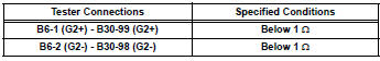
Standard resistance (check for short)
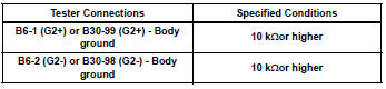
- Reconnect the ecm connector.
- Reconnect the cmp sensor connector.
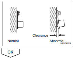
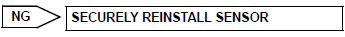
- Check sensor installation (camshaft position sensor)
- Check the cmp sensor installation.
Ok: sensor is installed correctly.
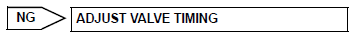
- Check valve timing (see page es-77)

- Check camshaft
- Check the teeth of the camshaft.
Ok: camshaft teeth do not have any cracks or deformation.


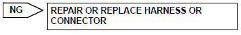
- Replace camshaft position sensor

- Check whether dtc output recurs
- Connect the intelligent tester to the dlc3.
- Turn the ignition switch on.
- Turn the tester on.
- Clear dtcs (see page es-35).
- Start the engine.
- Select the following menu items: diagnosis / enhanced obd ii / dtc info / pending codes.
- Read dtcs.


Hint:
If the engine does not start, replace the ecm.

 Crankshaft position sensor "A"
Description
The crankshaft position (ckp) sensor system consists of a ckp sensor plate
and a pickup coil.
The sensor plate has 34 teeth and is installed on the crankshaft. The pickup
coil ...
 Ignition coil
Description
Hint:
These dtcs indicate malfunctions relating to the primary circuit.
If dtc p0351 is set, check no. 1 Ignition coil with igniter circuit.
If dtc p0352 is set, check no. 2 I ...
Other materials:
Selecting the audio
source
Switching between audio sources such as radio and cd are
explained in this section.
Changing audio source
Press the “audio” button to display the audio source selection
screen.
If the audio source selection screen is not displayed, press the “audio”
button again.
Select the d ...
Reassembly
Hint:
When installing the ornament plate and emblem, heat the
radiator grille, ornament plate and emblem using a heat light.
Standard heating temperature
Notice:
Do not heat the radiator grille, ornament plate and
emblem excessively.
Install radiator grille emblem
Attach ...
Fog light relay
On-vehicle inspection
Inspect front fog light relay
Remove the front fog relay from the no. 6 Relay
block.
Measure the resistance of the relay.
Standard resistance
If the result is not as specified, replace the relay. ...
