Toyota RAV4 (XA40) 2013-2018 Service Manual: Ignition coil
Description
Hint:
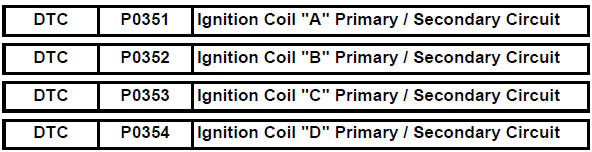
- These dtcs indicate malfunctions relating to the primary circuit.
- If dtc p0351 is set, check no. 1 Ignition coil with igniter circuit.
- If dtc p0352 is set, check no. 2 Ignition coil with igniter circuit.
- If dtc p0353 is set, check no. 3 Ignition coil with igniter circuit.
- If dtc p0354 is set, check no. 4 Ignition coil with igniter circuit.
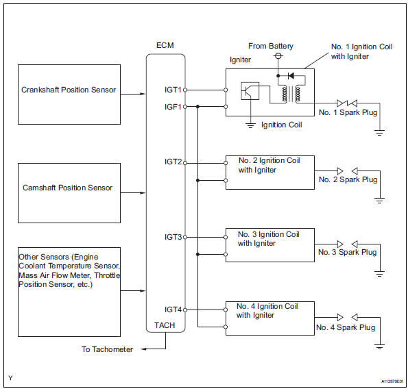
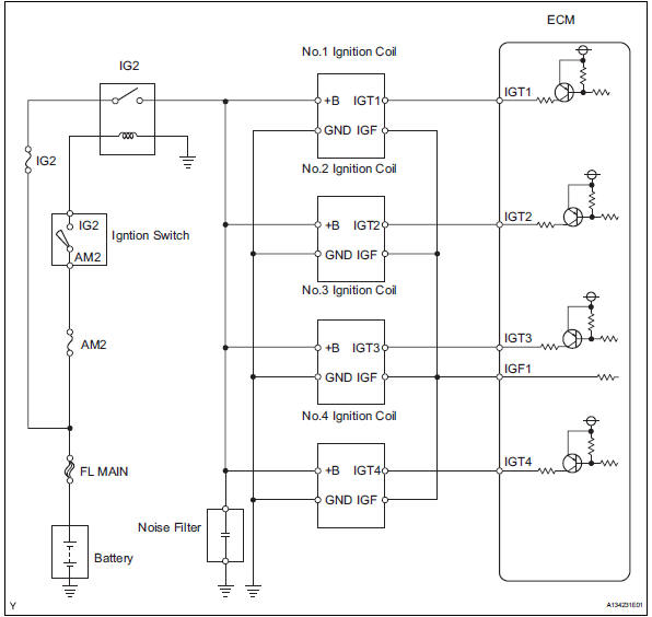
A direct ignition system (dis) is used on this vehicle.
The dis is a 1-cylinder ignition system in which each cylinder is ignited by one ignition coil and one spark plug is connected to the end of each secondary wiring. A powerful voltage, generated in the secondary wiring, is applied directly to each spark plug. The sparks of the spark plugs pass from the center electrode to the ground electrodes.
The ecm determines the ignition timing and transmits the ignition (igt) signals to each cylinder. Using the igt signal, the ecm turns the power transistor inside the igniter on and off. The power transistor, in turn, switches on and off the current to the primary coil. When the current to the primary coil is cut off, a powerful voltage is generated in the secondary coil. This voltage is applied to the spark plugs, causing them to spark inside the cylinders. As the ecm cuts the current to the primary coil, the igniter sends back an ignition confirmation (igf) signal to the ecm, for each cylinder ignition.
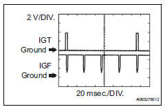
Reference: inspection using an oscilloscope.
While cranking or idling the engine, check the waveform between terminals igt (1
to 4) and e1, and igf1
and e1 of the ecm connector. 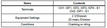
Monitor description
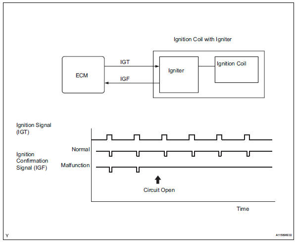
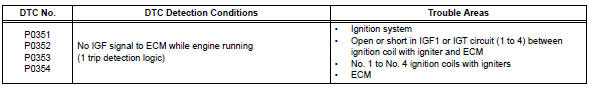
If the ecm does not receive any igf signals despite transmitting the igt signal, it interprets this as a fault in the igniter and sets a dtc.
If the malfunction is not repaired successfully, a dtc is set 1 second after the engine is next started.
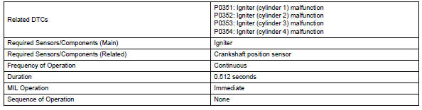
Monitor strategy
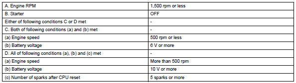
Typical enabling conditions
![]()
Typical malfunction thresholds
![]()
Component operating range
![]()
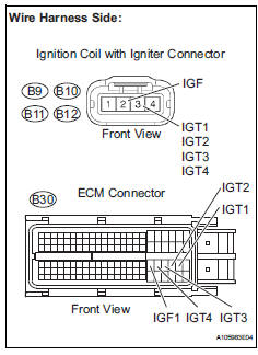
Wiring diagram
Inspection procedure
Hint:
Read freeze frame data using the intelligent tester. Freeze frame data records the engine condition when malfunctions are detected. When troubleshooting, freeze frame data can help determine if the vehicle was moving or stationary, if the engine was warmed up or not, if the air-fuel ratio was lean or rich, and other data from the time the malfunction occurred.
- Inspect ignition coil assembly (power source)
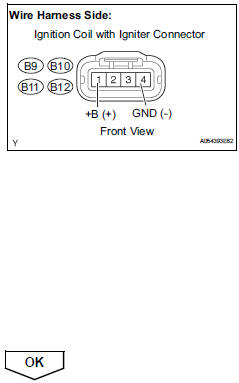
- Disconnect the ignition coil with igniter connector.
- Measure the resistance.
Standard resistance (check for open)
- Turn the ignition switch on.
- Measure the voltage between the terminals of the wire harness side connector.
Standard voltage 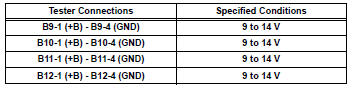
- Reconnect the ignition coil with igniter connector.
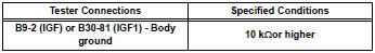
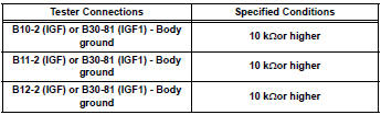
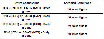
- Check harness and connector (ignition coil assembly - ecm)
- Disconnect the ignition coil with connector.
- Disconnect the b30 ecm connector.
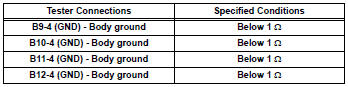
- Measure the resistance.
 Standard
resistance (check for open)
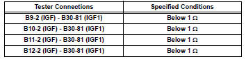
Standard resistance (check for open)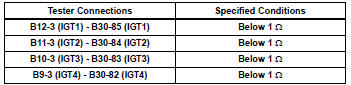
Standard resistance (check for short)
Standard resistance (check for short)
- Reconnect the ecm connector.
- Reconnect the ignition coil with igniter connector.

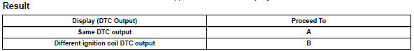
- Check whether dtc output recurs (dtc p0351, p0352, p0353 or p0354)
- Connect the intelligent tester to the dlc3.
- Turn the ignition switch on and turn the tester on.
- Clear dtcs (see page es-35).
- Shuffle arrangement of the ignition coils with igniters (among no. 1 To no. 4 Cylinders).
Notice:
Do not shuffle the connectors.
- Perform a simulation test.
- Check dtcs displayed on the tester.
 Camshaft position sensor "a" circuit (bank 1 or single sensor)
Description
The camshaft position (cmp) sensor consists of a magnet and an iron core
which is wrapped with copper
wire, and is installed onto the cylinder head. When the camshaft rotates, each ...
 Catalyst system efficiency below threshold (bank 1)
Monitor description
The ecm uses sensors mounted in front of and behind the three-way catalytic
converter (twc) to
monitor its efficiency.
The first sensor, the air-fuel ratio (a/f) sensor, ...
Other materials:
Diagnosis system
Description
The ecm controls the function of cruise control on this
vehicle. Data of the cruise control or dtc can be read
from the dlc3 of the vehicle. When trouble occurs with
cruise control, check that the cruise main indicator
does not come on but dtc inspection is performed.
Theref ...
Checking tires
Check if the treadwear indicators
are showing on the tires.
Also check the tires for uneven
wear, such as excessive wear
on one side of the tread.
Check the spare tire condition
and pressure if not rotated.
New tread
Worn tread
Treadwear indicator
The location of treadwear indicators
is show ...
Removal
Hint:
Use the same procedures for the rh side and lh side.
The procedures listed below are for the lh side.
Disconnect cable from negative battery
terminal
Caution:
Wait at least 90 seconds after disconnecting the
cable from the negative (-) battery terminal to
prevent airbag and ...
