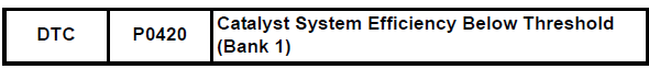
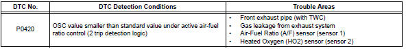
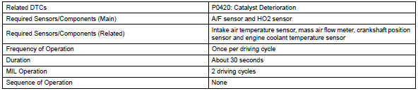
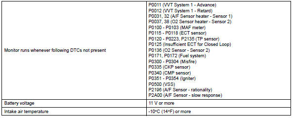
Toyota RAV4 (XA40) 2013-2018 Service Manual: Catalyst system efficiency below threshold (bank 1)
Monitor description
The ecm uses sensors mounted in front of and behind the three-way catalytic converter (twc) to monitor its efficiency.
The first sensor, the air-fuel ratio (a/f) sensor, sends pre-catalyst information to the ecm. The second sensor, the heated oxygen (ho2) sensor, sends post-catalyst information to the ecm.
In order to detect any deterioration in the twc, the ecm calculates the oxygen storage capacity (osc) of the twc. This calculation is based on the voltage output of the ho2 sensor while performing active airfuel ratio control, rather than the conventional detecting method, which uses the locus ratio.
The osc value is an indication of the oxygen storage capacity of the twc. When the vehicle is being driven with a warm engine, active air-fuel ratio control is performed for approximately 15 to 20 seconds.
When it is performed, the ecm deliberately sets the air-fuel ratio to lean or rich levels. If the rich-lean cycle of the ho2 sensor is long, the osc becomes greater. There is a direct correlation between the oscs of the ho2 sensor and the twc.
The ecm uses the osc value to determine the state of the twc. If any deterioration has occurred, it illuminates the mil and sets the dtc.
Monitor strategy
Typical enabling conditions
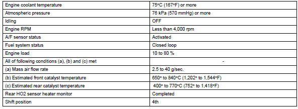
Typical malfunction thresholds
![]()
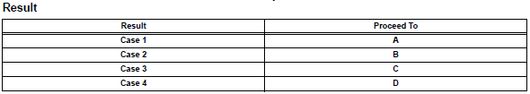
Monitor result
Refer to checking monitor status (see page es-17).
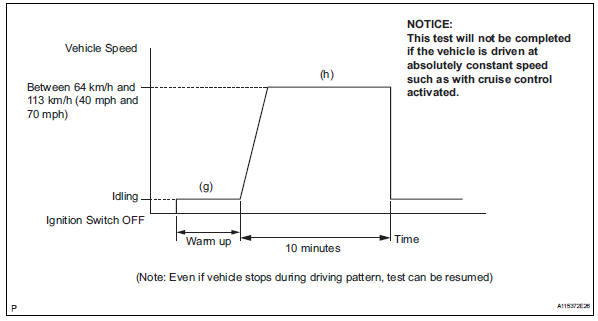
Confirmation driving pattern
Hint:
Performing this confirmation pattern will activate the catalyst monitor. This is very useful for verifying the completion of a repair.
- Connect the intelligent tester to the dlc3.
- Turn the ignition switch on.
- Turn the tester on.
- Clear dtcs (if set) (see page es-35).
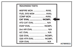
- Select the following menu items: diagnosis / enhanced obd ii / data list / user data / cat cmpl.
- Check that cat cmpl is incmpl (incomplete).
- Start the engine and warm it up.
- Drive the vehicle at between 64 km/h and 113 km/h (40 mph and 70 mph) for at least 10 minutes.
- Note the state of the readiness tests items. Those items will change to compl (complete) as cat cmpl monitor operates.
- On the tester, select the following menu items: diagnosis / enhanced obd ii / dtc info / pending codes and check if any dtcs (any pending dtcs) are set.
Hint:
If cat cmpl does not change to compl, and any pending dtcs fail to set, extend the driving time.
Conditioning for sensor testing
Hint:
Perform the operation with the engine speeds and time durations described below prior to checking the waveforms of the a/f and ho2 sensors. This is in order to activate the sensors sufficiently to obtain the appropriate inspection results.
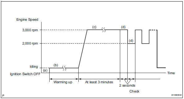
- Connect the intelligent tester to the dlc3.
- Start the engine and warm it up with all the accessories switched off, until the engine coolant temperature stabilizes.
- Run the engine at an engine speed of between 2,500 rpm and 3,000 rpm for at least 3 minutes.
- While running the engine at 3,000 rpm and 2,000 rpm alternating at 2 second intervals, check the waveforms of the a/f and ho2 sensors using the tester.
Hint:
- If either voltage output of the air-fuel ratio (a/f) or heated oxygen (ho2) sensor does not fluctuate, or there is a noise in the waveform of either sensor, the sensor may be malfunctioning.
- If the voltage outputs of both the sensors remain lean or rich, the air-fuel ratio may be extremely lean or rich. In such cases, perform the following a/f control using the intelligent tester.
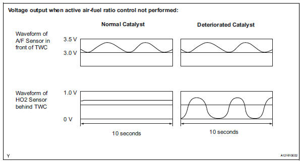
- If the three-way catalytic converter (twc) has deteriorated, the ho2 sensor (located behind the twc) voltage output fluctuates up and down frequently, even under normal driving conditions (active air-fuel ratio control is not performed)
Inspection procedure
Hint:
Read freeze frame data using the intelligent tester. Freeze frame data records the engine condition when malfunctions are detected. When troubleshooting, freeze frame data can help determine if the vehicle was moving or stationary, if the engine was warmed up or not, if the air-fuel ratio was lean or rich, and other data from the time the malfunction occurred.
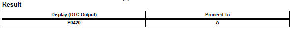
- Check any other dtcs output (in addition to dtc p0420)
- Connect the intelligent tester to the dlc3.
- Turn the ignition switch on and turn the tester on.
- Select the following menu items: diagnosis / enhanced obd ii / dtc info / current codes.
- Read dtcs.
![]()
Hint:
If any dtcs other than p0420 are output, troubleshoot those dtcs first.


- Perform active test using intelligent tester (a/f control)
- Connect the intelligent tester to the dlc3.
- Start the engine and turn the tester on.
- Warm up the engine at an engine speed of 2,500 rpm for approximately 90 seconds.
- On the tester, select the following menu items: diagnosis / enhanced obd ii / active test / a/f control.
- Perform the a/f control operation with the engine in an idling condition (press the right or left button to change the fuel injection volume).
- Monitor the voltage outputs of the a/f and ho2 sensors (afs b1 s1 and o2s b1 s2) displayed on the tester.
Result: a/f sensor reacts in accordance with increases and decreases in fuel injection volume: +25 % = rich output: less than 3.0 V
-12.5 % = Lean output: more than 3.35 V
Notice:
The a/f sensor has an output delay of a few seconds and the ho2 sensor has a maximum output delay of approximately 20 seconds.
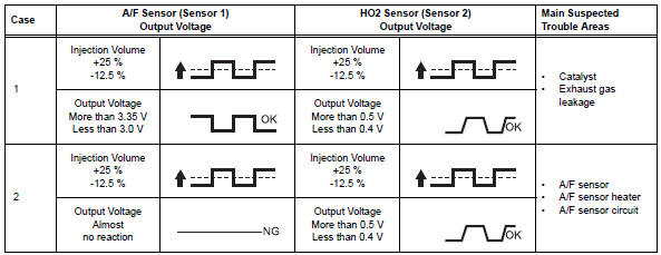
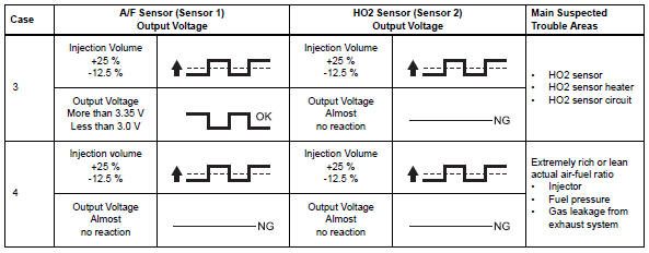
Following the a/f control procedure enables technicians to check and graph the voltage outputs of both the a/f and ho2 sensors.
To display the graph, select the following menu items on the tester: diagnosis / enhanced obd ii / active test / a/f control / user data / afs b1 s1 and o2s b1 s2; then press the yes button and then the enter button followed by the f4 button.

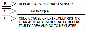
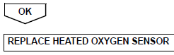
- Check for exhaust gas leakage
Ok: no gas leakage.

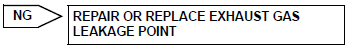
Replace three-way catalytic converter (both front and rear catalysts (front exhaust pipe))
- Check for exhaust gas leakage
Ok: no gas leakage.
 Ignition coil
Description
Hint:
These dtcs indicate malfunctions relating to the primary circuit.
If dtc p0351 is set, check no. 1 Ignition coil with igniter circuit.
If dtc p0352 is set, check no. 2 I ...
 Evaporative emission system reference orifice
Dtc summary
Hint:
The reference orifice is located inside the canister pump module.
Description
The description can be found in the evap (evaporative emission) system (see
page es-335).
...
Other materials:
System diagram
System diagram (2005/11-2006/01)
System diagram (2006/01- )
...
Problem symptoms table (2005/11-2006/01)
Hint:
Use the table below to help determine the cause of the
problem symptom. The potential causes of the symptoms are
listed in order of probability in the "suspected area" column of
the table. Check each symptom by checking the suspected
areas in the order they are listed. Replace p ...
Abnormal temperature inside
Description
The tire pressure warning valve and transmitter measures tire internal
temperature as well as tire
pressure, and transmits the information to the tire pressure monitor receiver
along with the transmitter id.
If the measured temperature is out of the specified range, the tire ...
