Toyota RAV4 (XA40) 2013-2018 Service Manual: Crankshaft position sensor "A"
Description
The crankshaft position (ckp) sensor system consists of a ckp sensor plate and a pickup coil.
The sensor plate has 34 teeth and is installed on the crankshaft. The pickup coil is made of wound copper wire, an iron core and magnet. The sensor plate rotates and, as each tooth passes through the pickup coil, a pulse signal is created. The pickup coil generates 34 signals per engine revolution. Based on these signals, the ecm calculates the crankshaft position and engine rpm. Using these calculations, the fuel injection time and ignition timing are controlled.
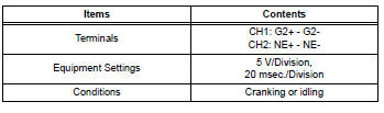
Reference: inspection using an oscilloscope.
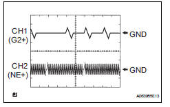
Hint:
- The correct waveform is as shown.
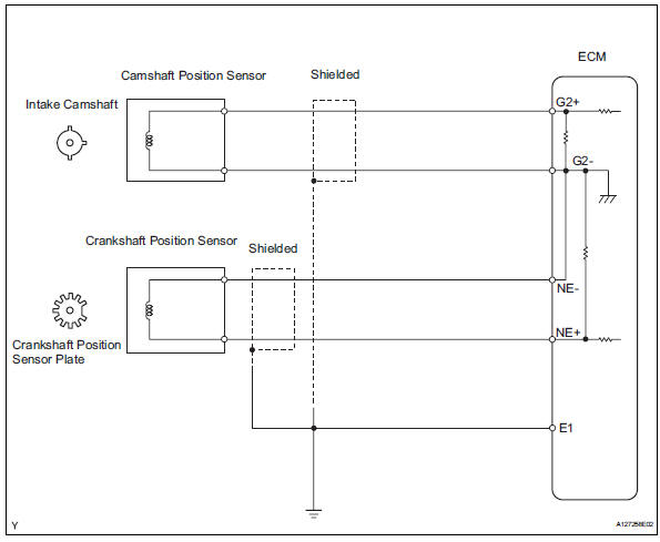
- G2+ stands for the camshaft position (cmp) sensor signal, and ne+ stands for the ckp sensor signal.
- Grounding failure of the shielded wire may cause noise in waveforms.
Monitor description
If there is no signal from the ckp sensor despite the engine revolving, the ecm interprets this as a malfunction of the sensor.
If the malfunction is not repaired successfully, a dtc is set 10 seconds after the engine is next started.
Monitor strategy
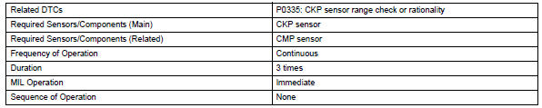
Typical enabling conditions
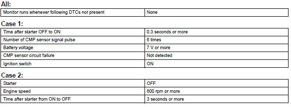
Typical malfunction thresholds
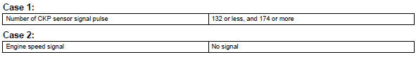
Component operating range
![]()
Wiring diagram
Inspection procedure
Hint:
- If no problem is found through this diagnostic troubleshoot procedure, troubleshoot the engine mechanical systems.
- Check the engine speed. The engine speed can be checked by using the intelligent tester. To check, follow the operation below:
- Connect the intelligent tester to the dlc3.
- Start the engine.
- Turn the tester on
- Select the following menu items: diagnosis / enhanced obd ii / data list / primary / engine spd.
The engine speed may be indicated as zero despite the engine revolving normally. This is caused by a lack of ne signals from the crankshaft position (ckp) sensor. Alternatively, the engine speed may be indicated as lower than the actual engine speed if the ckp sensor output voltage is insufficient.
- Read freeze frame data using the intelligent tester. Freeze frame data records the engine condition when malfunctions are detected. When troubleshooting, freeze frame data can help determine if the vehicle was moving or stationary, if the engine was warmed up or not, if the air-fuel ratio was lean or rich, and other data from the time the malfunction occurred.
- Read value using intelligent tester (engine spd)
- Connect the intelligent tester to the dlc3.
- Turn the ignition switch on.
- Turn the tester on.
- Select the following menu items: diagnosis / enhanced obd ii / data list / primary / engine spd.
- Start the engine.
- Read the values displayed on the tester while the engine is running.
Standard: correct values are displayed.
Hint:
- To check the engine speed change, display the graph on the tester.
- If the engine does not start, check the engine speed while cranking.
- If the engine speed indicated on the tester remains zero (0), there may be an open or short in the crankshaft position (ckp) sensor circuit.

- Inspect crankshaft position sensor (resistance)
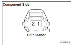
- Disconnect the b22 ckp sensor connector.
- Measure the resistance between terminals 1 and 2.
Standard resistance 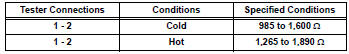
Hint:
Terms cold and hot refer to the temperature of the sensor. Cold means approximately -10 to 50°c (14 to 122°f). Hot means approximately 50 to 100°c (122 to 212°f).
- Reconnect the ckp sensor connector.

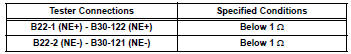
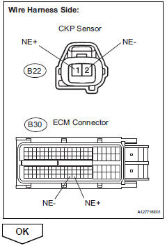
- Check harness and connector (crankshaft position sensor - ecm)
- Disconnect the b22 ckp sensor connector.
- Disconnect the b30 ecm connector.
- Measure the resistance.
Standard resistance (check for open)
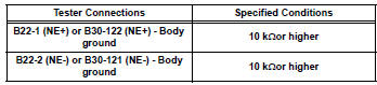
Standard resistance (check for short)
- Reconnect the ecm connector.
- Reconnect the ckp sensor connector.
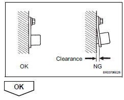
- Check sensor installation (crankshaft position sensor)
- Check the ckp sensor installation.
Ok: sensor is installed correctly.
- Check crankshaft position sensor plate (teeth of sensor plate)
- Check the teeth of the sensor plate.
Ok: sensor plate does not have any cracks or deformation.

- Replace crankshaft position sensor

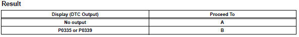
- Check whether dtc output recurs
- Connect the intelligent tester to the dlc3.
- Turn the ignition switch on.
- Turn the tester on.
- Clear dtcs (see page es-35).
- Start the engine.
- Select the following menu items: diagnosis / enhanced obd ii / dtc info / current codes.
- Read dtcs.
Hint:
If the engine does not start, replace the ecm.

 Knock sensor 1 circuit
Description
Flat type knock sensors (non-resonant type) have structures that can detect
vibrations over a wide band
of frequencies: between approximately 6 khz and 15 khz.
A knock sensor is ...
 Camshaft position sensor "a" circuit (bank 1 or single sensor)
Description
The camshaft position (cmp) sensor consists of a magnet and an iron core
which is wrapped with copper
wire, and is installed onto the cylinder head. When the camshaft rotates, each ...
Other materials:
Checking and replacing fuses
If any of the electrical components
do not operate, a
fuse may have blown. If this
happens, check and replace
the fuses as necessary.
Checking and replacing
fuses
1. Turn the engine switch to
OFF.
2. Open the fuse box cover.
Engine compartment: Type A
fuse box (if equipped)
Push claws A and B to co ...
General information
A large number of ecu controlled systems are used in the
rav4. In general, ecu controlled systems are considered to
be very intricate, requiring a high level of technical knowledge
to troubleshoot. However, most problem checking procedures
only involve inspecting the ecu controlled system's circ ...
Motor terminal voltage malfunction
Description
The power steering ecu supplies the current to the power steering motor
through the motor circuit.
Wiring diagram
Inspection procedure
Read value of intelligent tester (motor voltage)
Connect the intelligent tester (with can vim) to the
dlc3.
Turn the ignitio ...
