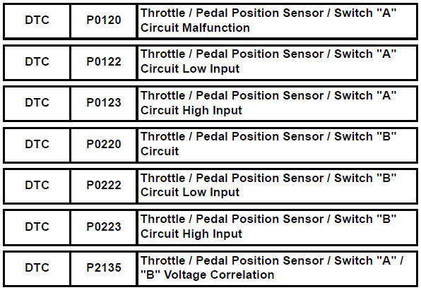
Toyota RAV4 (XA40) 2013-2018 Service Manual: Throttle / pedal position sensor / switch "A"
Hint:
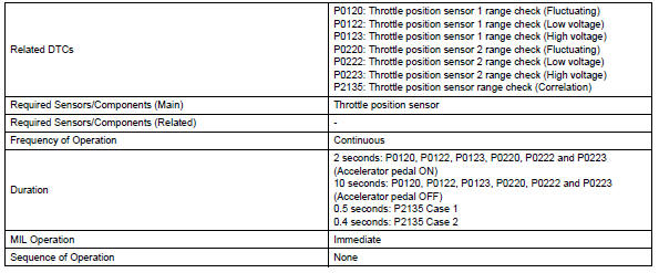
These dtcs relate to the throttle position (tp) sensor.
Description
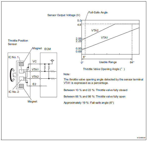
The tp sensor is mounted on the throttle body, and detects the opening angle of the throttle valve. This sensor is a non-contact type. It uses hall-effect elements in order to yield accurate signals even in extreme driving conditions, such as at high speeds as well as very low speeds.
The tp sensor has two sensor circuits which each transmits a signal, vta1 and vta2. Vta1 is used to detect the throttle valve angle and vta2 is used to detect malfunctions in vta1. The sensor signal voltages vary between 0 v and 5 v in proportion to the throttle valve opening angle, and are transmitted to the vta terminals of the ecm.
As the valve closes, the sensor output voltage decreases and as the valve opens, the sensor output voltage increases. The ecm calculates the throttle valve opening angle according to these signals and controls the throttle actuator in response to driver inputs. These signals are also used in calculations such as air-fuel ratio correction, power increase correction and fuel-cut control.
Hint:
- When any of these dtcs are set, check the throttle valve opening angle by selecting the following menu items the intelligent tester: diagnosis / enhanced obd ii / data list / etcs / throttle pos #1 and throttle pos #2.
- Throttle pos #1 denotes the vta1 signal, and throttle pos #2 denotes the vta2 signal.
Reference (normal condition)

Monitor description
The ecm uses the throttle position (tp) sensor to monitor the throttle valve opening angle. There are several checks that the ecm performs to confirm the proper operation of the tp sensor.
- A specific voltage difference is expected between the sensor terminals, vta1 and vta2, for each throttle valve opening angle. If the difference between vta1 and vta2 is incorrect, the ecm interprets this as a malfunction in the sensor, and sets a dtc.
- Vta1 and vta2 each have a specific voltage range. If vta1 or vta2 is outside the normal operating range, the ecm interprets this as a malfunction in the sensor, and sets a dtc.
- Vta1 and vta2 should never be close to the same voltage level. If vta1 is within 0.02 V of vta2, the ecm determines that there is a short circuit in the sensor, and sets a dtc.
If the malfunction is not repaired successfully, a dtc is set 10 seconds after the engine is next started.
Monitor strategy
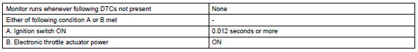
Typical enabling conditions
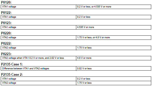
Typical malfunction thresholds
Component operating range
![]()
Fail-safe
When any of these dtcs, as well as other dtcs relating to etcs (electronic throttle control system) malfunctions, are set, the ecm enters fail-safe mode. During fail-safe mode, the ecm cuts the current to the throttle actuator off, and the throttle valve is returned to a 6° throttle angle by the return spring. The ecm then adjusts the engine output by controlling the fuel injection (intermittent fuel-cut) and ignition timing, in accordance with the accelerator pedal opening angle, to allow the vehicle to continue at a minimal speed. If the accelerator pedal is depressed firmly and gently, the vehicle can be driven slowly.
Fail-safe mode continues until a pass condition is detected, and the ignition switch is then turned off.
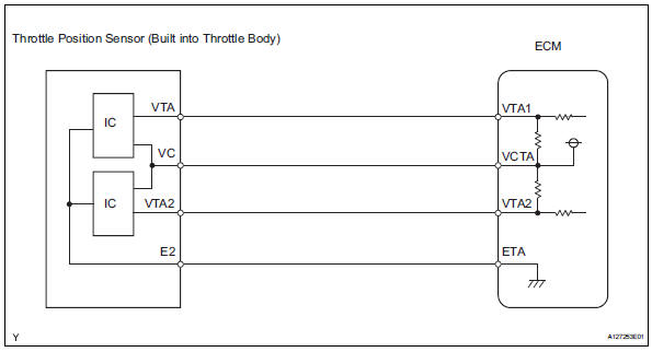
Wiring diagram
Inspection procedure
Hint:
Read freeze frame data using the intelligent tester. Freeze frame data records the engine condition when malfunctions are detected. When troubleshooting, freeze frame data can help determine if the vehicle was moving or stationary, if the engine was warmed up or not, if the air-fuel ratio was lean or rich, and other data from the time the malfunction occurred.
- Read value using intelligent tester (throttle pos #1 and throttle pos #2)
- Connect the intelligent tester to the dlc3.
- Turn the ignition switch on and turn the tester on.
- Select the following menu items: diagnosis / enhanced obd ii / data list / etcs / throttle pos #1 and throttle pos #2.
- Check the values displayed on the tester.
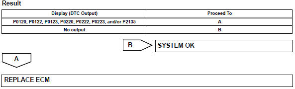
Result
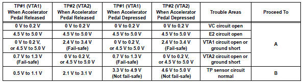
Hint:
Tp#1 denotes throttle pos #1, and tp#2 denotes throttle pos #2.


- Check harness and connector (throttle position sensor - ecm)
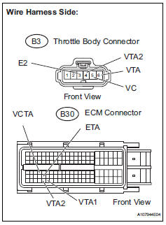
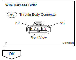
- Disconnect the b3 throttle body connector.
- Disconnect the b30 ecm connector.
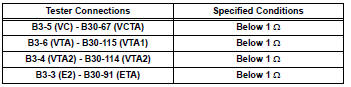
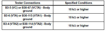
- Measure the resistance.
Standard resistance (check for open)
Standard resistance (check for short)
- Reconnect the throttle body connector.
- Reconnect the ecm connector.


- Inspect ecm (vc voltage)
- Disconnect the b3 throttle body connector.
- Turn the ignition switch on.
- Measure the voltage between the terminals of the throttle body connector.
Standard voltage 
- Reconnect the throttle body connector.
- Replace throttle body assembly

- Check whether dtc output recurs (throttle position sensor dtcs)
- Connect the intelligent tester to the dlc3.
- Turn the ignition switch on and turn the tester on.
- Clear dtcs (see page es-35).
- Start the engine.
- Allow the engine to idle for 15 seconds or more.
- Select the following menu items: diagnosis / enhanced obd ii / dtc info / current codes.
- Read dtcs.
 Engine coolant temperature circuit range / performance problem
Description
Refer to dtc p0115 (see page es-105).
Monitor description
Engine coolant temperature (ect) sensor cold start monitor
When a cold engine start is performed and then the engine i ...
 Throttle / pedal position sensor / switch "A" circuit range / performance
problem
Throttle / pedal position sensor / switch "A" circuit range / performance
problem
Hint:
This dtc relates to the throttle position (tp) sensor.
Description
Refer to dtc p0120 (see page es-114).
Monitor description
The ecm uses the tp sensor to monitor the throttle valve ...
Other materials:
Memory recall function (vehicles with a smart key system)
Each electronic key can be registered to recall your preferred driving
position.
Registering procedure
Record your driving position to button “1” or “2” before performing
the following:
carry only the key you want to register, and then close the driver’s
door.
If 2 or more keys ar ...
Propeller shaft system
Problem symptoms table
Hint:
Use the table below to help determine the cause of the
problem symptom. The potential causes of the symptoms are
listed in order of probability in the "suspected area" column of
the table. Check each symptom by checking the suspected
areas in the order th ...
How to proceed with troubleshooting
Hint:
Use these procedures to troubleshoot the lighting system.
*: Use the intelligent tester.
Vehicle brought to workshop
Inspect battery voltage
Standard voltage:
11 to 14 v
If the voltage is below 11 v, recharge or replace the battery
before proceeding.
Refer to pr ...
