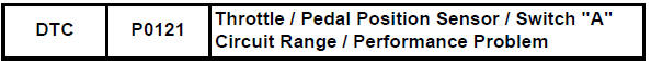
Toyota RAV4 (XA40) 2013-2018 Service Manual: Throttle / pedal position sensor / switch "A" circuit range / performance problem
Hint:
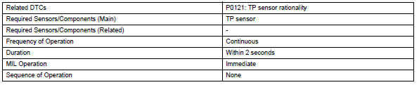
This dtc relates to the throttle position (tp) sensor.
Description
Refer to dtc p0120 (see page es-114).

Monitor description
The ecm uses the tp sensor to monitor the throttle valve opening angle.
This sensor transmits two signals: vta1 and vta2. Vta1 is used to detect the throttle opening angle and vta2 is used to detect malfunctions in vta1. The ecm performs several checks to confirm the proper operation of the tp sensor and vta1.
For each throttle opening angle, a specific voltage difference is expected between the outputs of vta1 and vta2. If the output voltage difference between the two signals deviates from the normal operating range, the ecm interprets this as a malfunction of the tp sensor. The ecm illuminates the mil and sets the dtc.
If the malfunction is not repaired successfully, the dtc is set 2 seconds after the engine is next started.
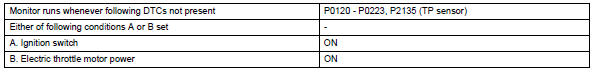
Monitor strategy
Typical enabling conditions
Typical malfunction thresholds
![]()
Fail-safe
When this dtc, as well as other dtcs relating to etcs (electronic throttle control system) malfunctions, is set, the ecm enters fail-safe mode. During fail-safe mode, the ecm cuts the current to the throttle actuator off, and the throttle valve is returned to a 6° throttle angle by the return spring. The ecm then adjusts the engine output by controlling the fuel injection (intermittent fuel-cut) and ignition timing, in accordance with the accelerator pedal opening angle, to allow the vehicle to continue at a minimal speed. If the accelerator pedal is depressed firmly and gently, the vehicle can be driven slowly.
Fail-safe mode continues until a pass condition is detected, and the ignition switch is then turned off.
Inspection procedure
Hint:
Read freeze frame data using the intelligent tester. Freeze frame data records the engine condition when malfunctions are detected. When troubleshooting, freeze frame data can help determine if the vehicle was moving or stationary, if the engine was warmed up or not, if the air-fuel ratio was lean or rich, and other data from the time the malfunction occurred.
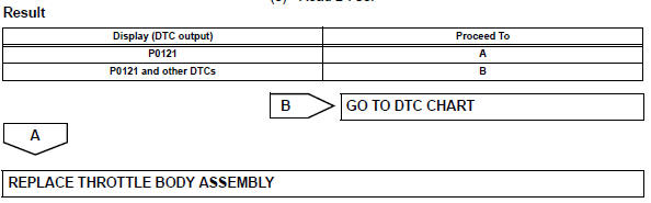
- Check any other dtcs output (in addition to dtc p0121)
- Connect the intelligent tester to the dlc3.
- Turn the ignition switch on.
- Turn the tester on.
- Select the following menu items: diagnosis / enhanced obd ii / dtc info / current codes.
- Read dtcs.
 Throttle / pedal position sensor / switch "A"
Hint:
These dtcs relate to the throttle position (tp) sensor.
Description
The tp sensor is mounted on the throttle body, and detects the opening angle
of the throttle valve. This
sensor is a ...
 Insufficient coolant temperature for closed loop fuel control
Description
Refer to dtc p0115 (see page es-105).
Monitor description
The resistance of the ect sensor varies in proportion to the actual ect. The
ect supplies a constant
voltage to the ...
Other materials:
Making a phone call
To enter the “phone” mode, press the off-hook switch.
Making a phone call
Dialing by inputting a name
Speed dialing
Dialing by entering the number
Dialing from call histories
Receiving a phone call
Answering the phone
Refusing the call
Operations during a call
Transfer ...
Map light assembly
Components
Removal
Disconnect cable from negative battery
terminal
Caution:
Wait at least 90 seconds after disconnecting the
cable from the negative (-) battery terminal to
prevent airbag and seat belt pretensioner activation.
Remove map light assembly
Detach the 4 cli ...
Freeze frame data
Description
Freeze frame data records the engine conditions (fuel
system, calculated load, engine coolant temperature,
fuel trim, engine speed, vehicle speed, etc.) When a
malfunction is detected. When troubleshooting, it can
help determine if the vehicle was running or stopped, the
engin ...
