Toyota RAV4 (XA40) 2013-2018 Service Manual: Front passenger side satellite sensor bus initialization incomplete
Description
When the center airbag sensor receives signals from the lateral deceleration sensor, it determines whether or not the srs should be activated.
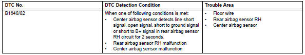
Dtc b1648/82 is recorded when a malfunction is detected in the rear airbag sensor rh circuit.
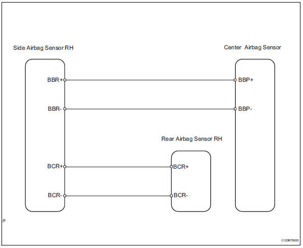
Wiring diagram
Inspection procedure
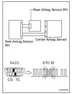
- Check for dtc
- Turn the ignition switch on, and wait for at least 60 seconds.
- Clear the dtcs (see page rs-49).
- Turn the ignition switch off.
- Turn the ignition switch on, and wait for at least 60 seconds.
- Check the dtcs (see page rs-49).
Ok: dtc b1627/82 is not output.
Dtc b1637/82 is not output.
Hint:
Dtcs other than dtc b1627/82 and b1637/82 may be output at this time, but they are not related to this check.

- Check connection of connector
- Turn the ignition switch off.
- Disconnect the cable from the negative (-) battery terminal, and wait for at least 90 seconds.
- Check that the connectors are properly connected to the center airbag sensor, rear airbag sensor rh and the side airbag sensor rh.
Ok: the connectors are properly connected.


- Check floor wire (open)
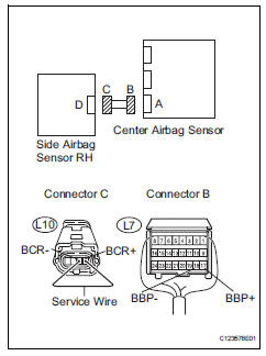
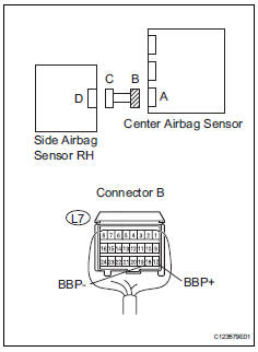
- Disconnect the connectors from the center airbag sensor and the side airbag sensor rh.
- Using a service wire, connect l10-4 (bbr+) and l10-3 (bbr-) of connector c.
Notice:
Do not forcibly insert the service wire into the terminals of the connector when connecting.
- Measure the resistance of the wire harness side connector.
Standard resistance 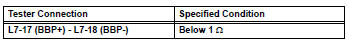

- Check floor wire (short)
- Disconnect the service wire from connector c.
- Measure the resistance of the wire harness side connector.
Standard resistance 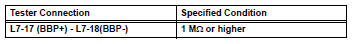

- Check floor wire (to b+)
- Connect the cable to the negative (-) battery terminal, and wait for at least 2 seconds.
- Turn the ignition switch on.
- Measure the voltage of the wire harness side connector.
Standard voltage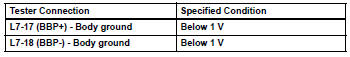

- Check floor wire (to ground)
- Turn the ignition switch off.
- Disconnect the cable from the negative (-) battery terminal, and wait for at least 90 seconds.
- Measure the resistance of the wire harness side connector.
Standard resistance 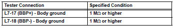

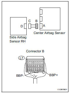
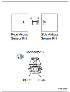
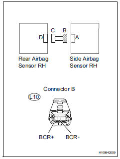
- Check floor wire (open)
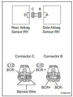
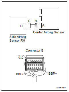
- Disconnect the connectors from the side airbag sensor rh and the rear airbag sensor rh.
- Using a service wire, connect l12-1 (bcr-) and l12-2 (bcr+) of connector c.
Notice:
Do not forcibly insert the service wire into the terminals of the connector when connecting.
- Measure the resistance of the wire harness side connector.
Standard resistance 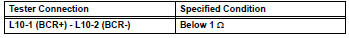

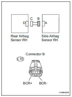
- Check floor wire (short)
- Disconnect the service wire from connector c.
- Measure the resistance of the wire harness side connector.
Standard resistance 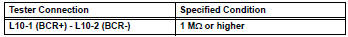

- Check floor wire (to b+)
- Connect the cable to the negative (-) battery terminal, and wait for at least 2 seconds.
- Turn the ignition switch on.
- Measure the voltage of the wire harness side connector.
Standard voltage 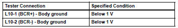


- Check floor wire (to ground)
- Turn the ignition switch off.
- Disconnect the cable from the negative (-) battery terminal, and wait for at least 90 seconds.
- Measure the resistance of the wire harness side connector.
Standard resistance 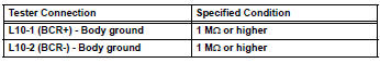

- Check side airbag sensor rh
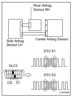
- Connect the connectors to the center airbag sensor.
- interchange the side airbag sensor rh with the side airbag sensor lh and connect the connectors to them.
- Connect the cable to the negative (-) battery terminal, and wait for at least 2 seconds.
- Turn the ignition switch on, and wait for at least 60 seconds.
- Clear the dtcs (see page rs-49).
- Turn the ignition switch off.
- Turn the ignition switch on, and wait for at least 60 seconds.
- Check for dtcs (see page rs-49).
Result 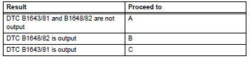
Hint:
Dtcs other than dtc b1643/81 or b1648/82 may be output at this time, but they are not related to this check.


- Check rear airbag sensor rh
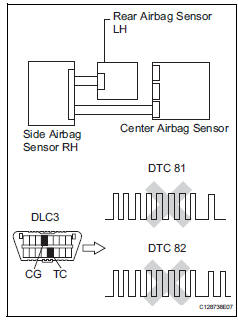
- Turn the ignition switch off.
- Disconnect the cable from the negative (-) battery terminal, and wait for at least 90 seconds.
- Interchange the rear airbag sensor lh with the rear airbag sensor rh and connect the connectors to them.
- Connect the cable to the negative (-) battery terminal, and wait for at least 2 seconds.
- Turn the ignition switch on, and wait for at least 60 seconds.
- Clear the dtcs (see page rs-49).
- Turn the ignition switch off.
- Turn the ignition switch on, and wait for at least 60 seconds.
- Check the dtcs (see page rs-49).
Result 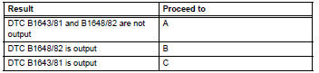

Use simulation method to check
 Driver side satellite sensor bus initialization incomplete
Description
The side airbag sensor lh consists of part including the diagnostic circuit
and the lateral deceleration
sensor.
When the center airbag sensor receives signals from the lateral ...
 Occupant classification system malfunction
Description
The occupant classification system circuit consists of the center airbag
sensor and the occupant
classification system.
When the center airbag sensor receives signals from the occup ...
Other materials:
Ig power source circuit
Description
This is the main power source supplied to the air conditioning amplifier when
the ignition switch is on.
This power source is used for operating components, such as the air conditioning
amplifier and servo
motors.
Wiring diagram
Inspection procedure
Inspect fuse (ecu-i ...
Turn signal lever
Operating instructions
Right turn
Lane change to the right (move
the lever partway and release
it)
the right hand signals will flash 3
times.
Lane change to the left (move
the lever partway and release
it)
the left hand signals will flash 3
times.
Left turn
Turn signals ...
Components
(2005/11-2006/01)
...
