
Toyota RAV4 (XA40) 2013-2018 Service Manual: Dtc check / clear
- Check dtc
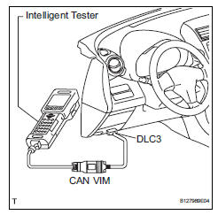
- Connect the intelligent tester (with can vim) to the dlc3.
- Turn the ignition switch on and turn the intelligent tester on.
- Read the dtc by following the prompts on the tester screen.
Hint:
Refer to the intelligent tester operator's manual for further details.
- Clear dtc
- Connect the intelligent tester (with can vim) to the dlc3.
- Turn the ignition switch on and turn the intelligent tester on.
- Clear the dtc by following the prompts on the tester screen.
Hint:
Refer to the intelligent tester operator's manual for further details.
 Diagnosis system
Description
Air conditioning system data and the diagnostic
trouble codes (dtcs) can be read through the
data link connector 3 (dlc3) of the vehicle. When
the system seems to be malfunc ...
 Check mode procedure
Panel diagnosis (indicator check)
Turn the ignition switch to lock.
Turn the ignition switch on while simultaneously
pressing the a/c control auto switch and the rec/
frs switch.
Chec ...
Other materials:
Front occupant classification sensor lh circuit
malfunction
Description
The front occupant classification sensor lh circuit consists of the occupant
classification ecu and the
front occupant classification sensor lh.
Dtc b1780 is recorded when a malfunction is detected in the front occupant
classification sensor lh
circuit.
Wiring diagram
...
Torque converter clutch solenoid circuit
Description
The shift solenoid valve dsl is turned on and off by signals from the ecm to
control the hydraulic
pressure acting on the lock-up relay valve, which then controls operation of the
lock-up clutch.
Fail-safe function:
if the ecm detects a malfunction, it turns the shift sol ...
Removal
Disconnect cable from negative battery
terminal
Caution:
Wait at least 90 seconds after disconnecting the
cable from the negative (-) battery terminal to
prevent airbag and seat belt pretensioner activation.
Remove no. 1 Engine cover (see page es-410)
Remove camshaft timing oil cont ...
