Toyota RAV4 (XA40) 2013-2018 Service Manual: Mil circuit
Description
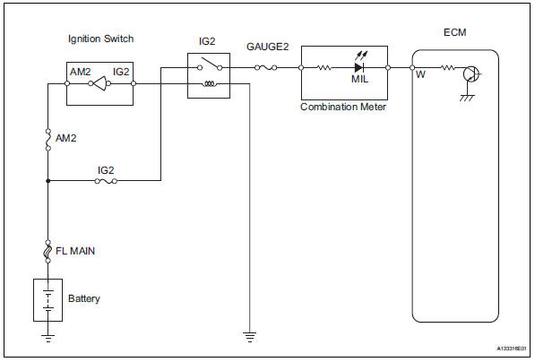
The mil (malfunction indicator lamp) is used to indicate vehicle malfunction detections by the ecm.
When the ignition switch is turned on, power is supplied to the mil circuit, and the ecm provides the circuit ground which illuminates the mil.
The mil operation can be checked visually: when the ignition switch is first turned on, the mil should be illuminated and should then turn off. If the mil remains illuminated or is not illuminated, conduct the following troubleshooting procedure using the intelligent tester.
Wiring diagram
Inspection procedure
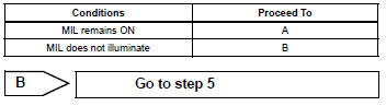
- Check that mil is illuminated
- Perform troubleshooting in accordance with the table below.

- Check whether mil turns off
- Connect the intelligent tester to the dlc3.
- Turn the ignition switch on and turn the tester on.
- Select the following menu items: diagnosis / enhanced obd ii / dtc info / current codes.
- Check if any dtcs have been stored. Note down any dtcs.
- Clear dtcs (see page es-35).
- Check if the mil goes off.
Standard: mil should go off.

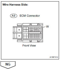
- Check harness and connector (check for short in wire harness)
- Disconnect the a9 ecm connector.
- Turn the ignition switch on.
- Check that the mil is not illuminated.
Ok: mil is not illuminated.
- Reconnect the ecm connector.
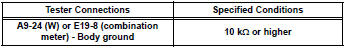
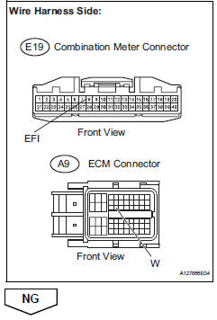
- Check harness and connector (combination meter - ecm)
- Disconnect the a9 ecm connector.
- Disconnect the e19 combination meter connector.
- Measure the resistance.
Standard resistance (check for short)
- Reconnect the ecm connector.
- Reconnect the combination meter connector.

- Check that mil is illuminated
- Check if the mil is illuminated when the ignition switch is turned on.
Ok: mil should be illuminated.

- Check that engine starts
- Turn the ignition switch on.
- Start the engine.
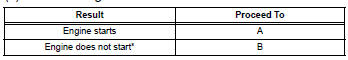
Hint:
*: The intelligent tester cannot communicate with the ecm.

- Inspect combination meter assembly (mil circuit)
- Check the mil circuit (see page me-15).

![]()
 Fuel pump control circuit
Description
When the engine is cranked, the starter relay drive signal output from the
star terminal of the ecm is
input into the sta terminal of the ecm, and ne signal generated by the
cranksha ...
 Mass air flow meter
Components
...
Other materials:
Short in driver side curtain shield squib circuit
Description
The driver side curtain shield squib circuit consists of the center airbag
sensor and the curtain shield
airbag lh.
The circuit instructs the srs to deploy when the deployment conditions are met.
These dtcs are recorded when a malfunction is detected in the driver side
cu ...
Hitch
Trailer hitch assemblies have different weight capacities. Toyota recommends
the use of toyota hitch/bracket for your vehicle. For details,
contact your toyota dealer.
If you wish to install a trailer hitch, contact your toyota dealer.
Use only a hitch that conforms to the gross trailer weig ...
Basic inspection
When a malfunction is not confirmed by the dtc check,
troubleshooting should be carried out in all circuits
considered to be possible causes of the problem. In many
cases, by carrying out the basic engine check shown in the
following flowchart, the location of the problem can be found
quickly a ...
