Toyota RAV4 (XA40) 2013-2018 Service Manual: Rear seat inner belt assembly
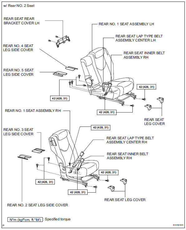
Components
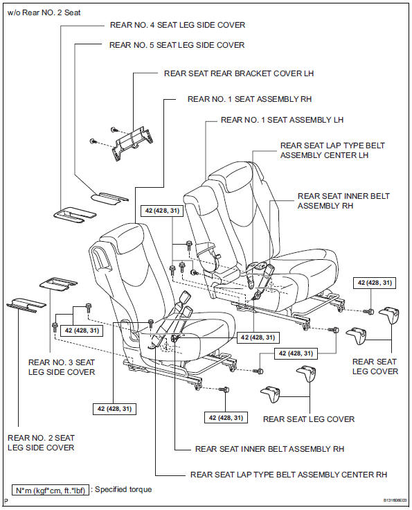
Removal
- Remove rear seat leg cover
- Remove rear no. 2 Seat leg side cover
- Remove rear no. 3 Seat leg side cover (w/ rear no. 2 Seat) (see page se-81)
- Remove rear no. 3 Seat leg side cover (w/o rear no. 2 Seat) (see page se-81)
- Remove rear no. 4 Seat leg side cover
- Remove rear no. 5 Seat leg side cover
- Remove rear seat lap type belt assembly center rh (w/o rear no. 2 Seat)
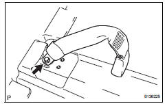
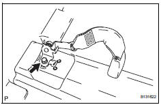
- Remove the bolt and seat belt.
- Remove rear seat lap type belt assembly center rh (w/ rear no. 2 Seat)
- Remove the bolt and seat belt.
- Remove rear no. 1 Seat assembly lh (see page se-50)
- Remove rear seat rear bracket cover lh (see page se-54)
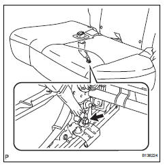
- Remove rear seat lap type belt assembly center lh
- Remove the bolt and the seat belt.
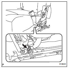
- Remove rear seat inner belt assembly rh (for 60/40 split seat type lh side)
- Remove the bolt and the seat belt.
- Remove rear no. 1 Seat assembly rh (see page se-84)
- Remove rear seat inner belt assembly rh (for 60/40 split seat type rh side)
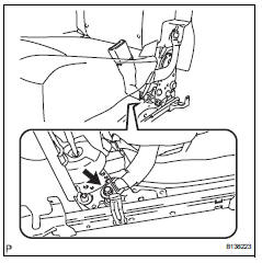
- Remove the bolt and the seat belt.
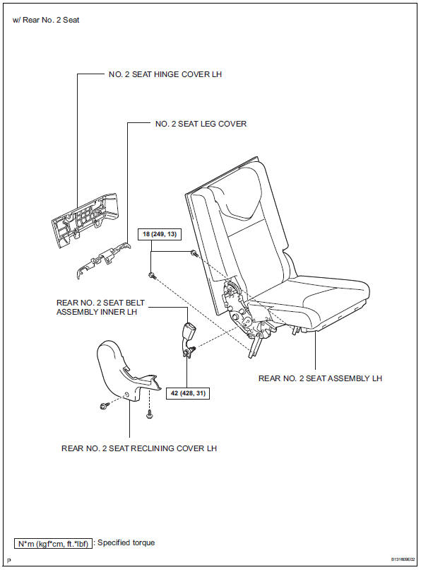
- Remove no. 2 Seat hinge cover lh (w/ rear no.
2 Seat) (see page se-109)
- Remove no. 2 Seat leg cover (w/ rear no. 2 Seat) (see page se-109)
- Remove rear no. 2 Seat assembly lh (w/ rear no. 2 Seat) (see page se-110)
- Remove rear no. 2 Seat reclining cover lh (w/ rear no. 2 Seat) (see page se-111)
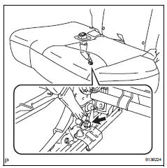
- Remove rear no. 2 Seat inner belt assembly lh (w/ rear no. 2 Seat)
- Remove the bolt and seat belt.
Installation
- Install rear no. 2 Seat inner belt assembly lh (w/ rear no. 2 Seat)
- Install the seat belt with the bolt.
Torque: 42 n*m (428 kgf*cm, 31 ft.*Lbf)
- Install rear no. 2 Seat reclining cover lh (w/ rear no. 2 Seat) (see page se-121)
- Install rear no. 2 Seat assembly lh (w/ rear no. 2 Seat) (see page se-121)
- Install no. 2 Seat leg cover (w/ rear no. 2 Seat) (see page se-123)
- Install no. 2 Seat hinge cover (w/ rear no. 2 Seat) (see page se-123)
- Install rear seat inner belt assembly rh (for 60/40 split seat type rh side)
- Install the belt with the bolt.
Torque: 42 n*m (428 kgf*cm, 31 ft.*Lbf)
- Install rear no. 1 Seat assembly rh (see page se-97)
- Install rear seat inner belt assembly rh (for 60/40 split seat type lh side)
- Install the belt with the bolt.
Torque: 42 n*m (428 kgf*cm, 31 ft.*Lbf)
- Install rear seat lap type belt assembly center lh
- Install the belt with the bolt.
Torque: 42 n*m (428 kgf*cm, 31 ft.*Lbf)
- Install rear seat rear bracket cover lh (see page se-60)
- Install rear no. 1 Seat assembly lh (see page se-64)
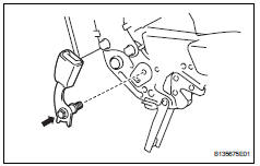
- Install rear seat lap type belt assembly center rh (w/o rear no. 2 Seat)
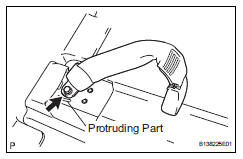
- Install the belt with the bolt.
Torque: 42 n*m (428 kgf*cm, 31 ft.*Lbf)
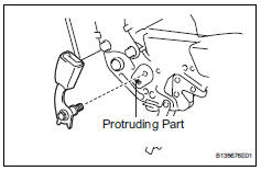
Notice:
The anchor part of the seat belt must not overlap the protruding part.
- Install rear seat lap type belt assembly center rh (w/ rear no. 2 Seat)
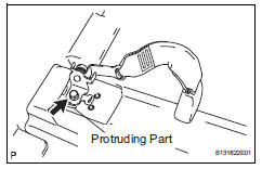
- Install the belt with the bolt.
Torque: 42 n*m (428 kgf*cm, 31 ft.*Lbf)
Notice:
The anchor part of the seat belt must not overlap the protruding part.
- Install rear no. 5 Seat leg side cover
- Install rear no. 4 Seat leg side cover
- Install rear no. 3 Seat leg side cover (w/ rear no. 2 Seat) (see page se-72)
- Install rear no. 3 Seat leg side cover (w/o rear no. 2 Seat) (see page se-72)
- Install rear no. 2 Seat leg side cover
- Install rear seat leg cover
 Disposal
Hint:
When scrapping vehicles equipped with a seat belt
pretensioner or disposing of a front seat outer belt (with seat
belt pretensioner), always first activate the seat belt
pretensioner in acco ...
 Rear seat outer belt assembly
Components
...
Other materials:
Installation
Hint:
Use the same procedures for the rh side and lh side.
The procedures listed below are for the lh side.
Install no. 2 Seat leg box protector
Attach the clip to install the protector.
Install the clip.
Install rear no. 1 Floor mat support side plate
Install rear no ...
Front drive shaft assembly (for 2wd)
Components (2005/11-2006/01)
Components (2006/01- )
...
Garage door opener
The garage door opener can
be programmed using the
HomeLink to operate
garage doors, gates, entry
doors, door locks, home
lighting systems, security
systems, and other devices.
â– HomeLink programming procedure
The programming procedures can
also be found at the following URL.
System components
The ...
