Toyota RAV4 (XA40) 2013-2018 Service Manual: Problem symptoms table
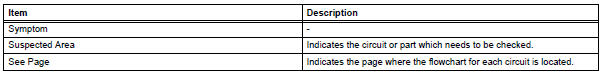
When a "normal" code is output during a dtc check but the problem is still occurring, use the problem symptoms table. The suspected areas (circuits or parts) for each problem symptom are in the table. The suspected areas are listed in order of probability. A description of each of the chart's columns is below.
Hint: in some cases, the problem is not detected by the diagnostic system even though a problem symptom is present. It is possible that the problem is occurring outside the detection range of the diagnostic system, or that the problem is occurring in a completely different system.
 Diagnostic trouble code chart
Look for output diagnostic trouble codes (dtcs) (from the
dtc checks) in the appropriate section's diagnostic trouble
code chart. Use the chart to determine the trouble area and
the proper inspecti ...
 Circuit inspection
A description of the main areas of each circuit inspection
is below.
Item
Description
description
The major role, operation of the circuit and its component parts are
explai ...
Other materials:
Other interior features
Sun visors
To set the visor in the forward
position, flip it down.
To set the visor in the side
position, flip down, unhook,
and swing it to the side.
To use the side extender (if
equipped), place the visor in
the side position, then slide it
backward.
Vanity mirrors
Slide the cover to o ...
Removal
Hint:
When removing the spoiler, heat the vehicle body and spoiler
using a heat light.
Standard heating temperature
Notice:
Do not heat the vehicle body and spoiler excessively.
Disconnect cable from negative battery
terminal
Caution:
Wait at least 90 seconds after disconnecting the
...
Torque converter clutch solenoid performance (shift solenoid valve dsl)
Description
The ecm uses the signals from the throttle position sensor, air-flow meter,
turbine (input) speed sensor,
intermediate (counter) shaft speed sensor and crankshaft position sensor to
monitor the engagement
condition of the lock-up clutch.
Then the ecm compares the engagement ...
